Moxa Technologies NPort 5200A Series User Manual
Hide thumbs
Also See for NPort 5200A Series:
- Quick installation manual (2 pages) ,
- User manual (194 pages)

Related Manuals for Moxa Technologies NPort 5200A Series


Summary of Contents for Moxa Technologies NPort 5200A Series
- Page 1 NPort 5200A Series User’s Manual First Edition, July 2010 www.moxa.com/product © 2010 Moxa Inc. All rights reserved. Reproduction without permission is prohibited.
- Page 2 NPort 5200A Series User’s Manual The software described in this manual is furnished under a license agreement and may be used only in accordance with the terms of that agreement. Copyright Notice Copyright ©2010 Moxa Inc. All rights reserved. Reproduction without permission is prohibited.
-
Page 3: Table Of Contents
Package Checklist ..........................1-2 Product Features ..........................1-2 Product Specifications ......................... 1-3 Getting Started..........................2-1 Panel Layout of the NPort 5200A Series ....................2-2 Connecting the Hardware........................2-2 Connecting the Power ........................2-2 Connecting to the Network ......................2-3 Connecting to a Serial Device ....................... 2-3 LED Indicators .......................... - Page 4 Configuring the NPort 5200A ......................6-8 Upgrading the Firmware ....................... 6-9 Export Configuration ........................6-10 Import Configuration ......................... 6-10 Monitor............................6-11 Port Monitor ............................. 6-14 COM Mapping ........................... 6-15 On-line COM Mapping ........................ 6-15 Off-line COM Mapping ........................ 6-19 COM Grouping ..........................6-20 Creating a COM Group .......................
-
Page 5: Introduction
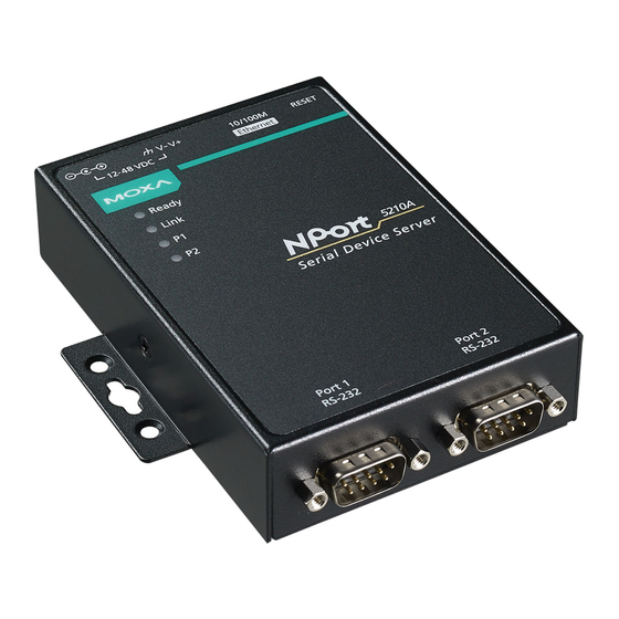
The NPort 5200A and NPort 5200A-T are advanced, 2-port RS-232/422/485 serial device servers that make it easy to network-enable serial devices. The NPort 5200A Series includes 6 models: NPort 5210A/5210A-T (2 ports for RS-232), NPort 5230A/5230A-T (2 ports for RS-422/485), and NPort 5250A/5250A-T (2 ports for RS-232/422/485). -
Page 6: Overview
Introduction Overview NPort 5200A series device servers are designed to make your industrial serial devices Internet ready instantly. The compact size of NPort 5200A device servers makes them the ideal choice for connecting your RS-232/422/485 serial devices, such as PLCs, meters, and sensors, to an IP-based Ethernet LAN, making it possible for your software to access serial devices located anywhere on a local LAN, or the Internet. -
Page 7: Product Specifications
NPort 5200A Series Introduction Product Specifications Ethernet Interface Number of Ports: 1 Speed: 10/100 Mbps, auto MDI/MDIX Connector: 8-pin RJ45 Magnetic Isolation Protection: 1.5 KV built-in Serial Interface Number of Ports: 2 Serial Standards: NPort® 5210A: RS-232 NPort® 5230A: RS-422/485 NPort®... - Page 8 NPort 5200A Series Introduction Power Requirements Input Voltage: 12 to 48 VDC Power Consumption: 119 mA @ 12V, 65 mA @ 24V Regulatory Approvals Power Line Protection: Level 2 Burst (EFT), EN61000-4-4, Level 3 Surge, EN61000-4-5 EMC: CE (EN55022 Class A, EN55024), FCC Part 15 Subpart B Class A...
-
Page 9: Getting Started
Getting Started This chapter includes information about installing the NPort 5200A. The following topics are covered in this chapter: Panel Layout of the NPort 5200A Series Connecting the Hardware Connecting the Power Connecting to the Network ... -
Page 10: Panel Layout Of The Nport 5200A Series
NPort 5200A Series Getting Started Panel Layout of the NPort 5200A Series Connecting the Hardware This section describes how to connect the NPort 5200A to serial devices for first time testing purposes. Connecting the Power Connect the 12 to 48 VDC power code with the NPort 5200A’s power input. If the power is properly supplied, the “Ready”... -
Page 11: Connecting To The Network
NPort 5200A Series Getting Started Connecting to the Network Connect one end of the Ethernet cable to the NPort 5200A’s 10/100M Ethernet port and the other end of the cable to the Ethernet network. The NPort 5200A will indicate a valid connection to the Ethernet in the following ways: •... - Page 12 NPort 5200A Series Getting Started NPort 5230A/5250A DIP Switches Pull-high resistor Pull-low resistor Terminator 1 KΩ 1 KΩ 120 Ω 150 KΩ* 150 KΩ* –* * Default...
-
Page 13: Initial Ip Address Configuration
Initial IP Address Configuration When setting up your NPort 5200A for the first time, you should first configure the IP address. This chapter introduces the method to configure the device server’s IP address. For more details about network settings, see the Network Settings section from Chapter 5, Web Console Configuration. -
Page 14: Initializing The Nport 5200A's Ip Address
NPort 5200A Series Initial IP Address Configuration Initializing the NPort 5200A’s IP Address Determine whether your NPort 5200A needs to use a Static IP or Dynamic IP (either DHCP or BOOTP application). If the NPort 5200A is used in a Static IP environment, you can use NPort Administration Suite, ARP, Web Console, Telnet Console, or Serial Console to configure the new IP address. -
Page 15: Telnet Console
NPort 5200A Series Initial IP Address Configuration 3. Execute the ‘arp -s’ command from your computer’s MS-DOS prompt by typing: arp –s 192.168.200.100 00-90-E8-xx-xx-xx This is where 192.168.200.100 is the new IP address and 00-90-E8-xx-xx-xx is the MAC address for your NPort 5200A (be sure to use the numbers determined in steps 1 and 2). - Page 16 NPort 5200A Series Initial IP Address Configuration 4. Type 2 to select Network settings, and then press Enter. 5. Type 1 to select IP address and then press Enter. 6. Use the Backspace key to erase the current IP address, type in the new IP address, and then press Enter.
- Page 17 NPort 5200A Series Initial IP Address Configuration 7. Press any key to continue. 8. Type m and then press Enter to return to the main menu. 9. Type s and then press Enter to Save/Restart the system. 10. Type y and then press Enter to save the new IP address and restart the NPort 5200A.
-
Page 18: Serial Console (19200, N, 8, 1) (Nport 5210A/5250A Only)
NPort 5200A Series Initial IP Address Configuration Serial Console (19200, n, 8, 1) (NPort 5210A/5250A only) You may use the RS-232 console port to set up the IP address for NPort 5200A. We suggest using PComm Terminal Emulator, which is available free of charge as part of the PComm Lite program suite (found on the Software CD that comes with the product), to carry out the installation procedure, although other similar utilities may also be used. - Page 19 NPort 5200A Series Initial IP Address Configuration 9. Start configuring the IP address under Network Settings. Refer to step 4 in the Telnet Console section for the rest of the IP settings.
-
Page 20: Choosing The Proper Operation Mode
Choosing the Proper Operation Mode In this section, we describe the various NPort 5200A operation modes. The options include Real COM Mode, which uses a driver installed on the host computer, and operation modes that rely on TCP/IP socket programming concepts. After choosing the proper operation mode in this chapter, refer to Chapter 5 for detailed configuration parameter definitions. -
Page 21: Overview
NPort 5200A Series Choosing the Proper Operation Mode Overview NPort 5200A serial device servers network-enable traditional RS-232/422/485 devices, in which a serial device server is a tiny computer equipped with a CPU, real-time OS, and TCP/IP protocols that can bi-directionally translate data between the serial and Ethernet formats. -
Page 22: Rfc 2217 Mode
NPort 5200A Series Choosing the Proper Operation Mode ATTENTION Real COM Mode allows several hosts to have access control to the same NPort 5200A. The driver that comes with your NPort 5200A controls host access to attached serial devices by checking the host’s IP address. Refer to the Accessible IP Settings section of Chapter 5 for more details. -
Page 23: Udp Mode
NPort 5200A Series Choosing the Proper Operation Mode UDP Mode Compared to TCP communication, UDP is faster and more efficient. In UDP mode, you can unicast or multicast data from the serial device to one or multiple host computers, and... -
Page 24: Reverse Telnet Mode
NPort 5200A Series Choosing the Proper Operation Mode Reverse Telnet Mode Console management is commonly used by connecting to Console/AUX or COM ports of routers, switches, and UPS units. Rtelnet works the same as TCP Server mode in that only one TCP port is listened to after booting up. -
Page 25: Web Console Configuration
Web Console Configuration The Web Console is the most user-friendly method available to configure the NPort 5200A. In this chapter, we introduce the Web Console function groups and function definitions. The following topics are covered in this chapter: Opening Your Browser ... -
Page 26: Opening Your Browser
NPort 5200A Series Web Console Configuration Opening Your Browser 1. Open your browser with the cookie function enabled. (To enable your browser for cookies, right click on your desktop Internet Explorer icon, select Properties, click on the Security tab, and then select the three Enable options as shown in the figure below.) -
Page 27: Quick Setup
NPort 5200A Series Web Console Configuration 4. The NPort 5200A homepage will open next. There are two buttons on this page: Quick setup and Export/Import. You can click Overview at any time to go back to this page. The following sections introduce these two convenient functions and all the other specific settings in the left Main Menu. - Page 28 NPort 5200A Series Web Console Configuration Step 1/3 In Step 1/3, you must assign a valid IP address to the NPort 5200A before it will work in your network environment. Your network system administrator should provide you with an IP address and related settings for your network.
-
Page 29: Export/Import
NPort 5200A Series Web Console Configuration Finish Settings Review your settings at the Finish Settings page to confirm that they are correct, and then click the Save/Restart button to restart the device with the new settings. NOTE If you changed the IP address, you will not be able to return to the Home Page with the Home button. -
Page 30: Basic Settings
NPort 5200A Series Web Console Configuration Basic Settings Server name Setting Factory Default Necessity 1 to 39 characters NP[model name]_[Serial No.] Optional This option is useful for specifying the location or application of different NPort 5200A units. Time The NPort 5200A has a built-in Real-Time Clock for time calibration functions. Real-time information can be added to Auto warning “Email”... -
Page 31: Network Settings
NPort 5200A Series Web Console Configuration Web/Telnet Console The “Disable” option for “Web Console” and “Telnet Console” is included for security reasons. In some cases, you may want to disable one or both of these console utilities as an extra precaution to prevent unauthorized users from accessing your NPort 5200A. - Page 32 NPort 5200A Series Web Console Configuration IP configuration Method Function Definition Static User defined IP address, Netmask, Gateway. DHCP DHCP Server assigned IP address, Netmask, Gateway, DNS, and Time Server DHCP/BOOTP DHCP Server assigned IP address, Netmask, Gateway, DNS, and Time Server, or BOOTP...
- Page 33 NPort 5200A Series Web Console Configuration When the user wants to visit a particular website, the computer asks a Domain Name System (DNS) server for the website’s correct IP address, and then the computer uses the response to connect to the web server. DNS is the way that Internet domain names are identified and translated into IP addresses.
-
Page 34: Serial Settings
NPort 5200A Series Web Console Configuration Auto report to IP Setting Factory Default Necessity E.g., 192.168.1.1 or URL None Optional (IP addresses of the form x.x.x.0 and x.x.x.255 are invalid.) Reports generated by the Auto report function will be automatically sent to this IP address. - Page 35 NPort 5200A Series Web Console Configuration Port alias Setting Factory Default Necessity 1 to 15 characters None Optional (E.g., PLC-No.1) “Port alias” is included to allow easy identification of the serial devices that are connected to the NPort 5200A’s serial port.
-
Page 36: Operating Settings
NPort 5200A Series Web Console Configuration Operating Settings Click Operating Settings, located under Main Menu, to display the operating settings for both of the NPort 5200A’s serial ports. Real COM Mode TCP alive check time Setting Factory Default Necessity 0 to 99 min... - Page 37 NPort 5200A Series Web Console Configuration Max connection Setting Factory Default Necessity 1, 2, 3, 4, 5, 6, 7, 8 Required Max connection is usually used when the user needs to receive data from different hosts simultaneously. The factory default is 1. In this case, only one specific host can access this port of the NPort 5200A, and the Real COM driver on that host will have full control over the port.
- Page 38 NPort 5200A Series Web Console Configuration Delimiter 1 Setting Factory Default Necessity 00 to FF (hex) None Optional Delimiter 2 Setting Factory Default Necessity 00 to FF (hex) None Optional Once the NPort 5200A receives both delimiters through its serial port, it immediately packs all data currently in its buffer and sends it to the NPort 5200A’s Ethernet port.
-
Page 39: Rfc 2217 Mode
NPort 5200A Series Web Console Configuration RFC 2217 Mode TCP alive check time Setting Factory Default Necessity 0 to 99 min 7 min Optional 0 min: TCP connection is not closed due to an idle TCP connection. 1 to 99 min: The NPort 5200A automatically closes the TCP connection if there is no TCP activity for the given time. - Page 40 NPort 5200A Series Web Console Configuration Delimiter process Setting Factory Default Necessity Do Nothing, Do Nothing Optional Delimiter + 1, Delimiter + 2, Strip Delimiter [Delimiter + 1] or [Delimiter + 2]: The data will be transmitted when an additional byte (for Delimiter +1), or an additional 2 bytes (for Delimiter +2) of data is received after receiving the Delimiter.
-
Page 41: Tcp Server Mode
NPort 5200A Series Web Console Configuration TCP Server Mode TCP alive check time Setting Factory Default Necessity 0 to 99 min 7 min Optional 0 min: TCP connection is not closed due to an idle TCP connection. 1 to 99 min: The NPort 5200A automatically closes the TCP connection if there is no TCP activity for the given time. - Page 42 NPort 5200A Series Web Console Configuration Max connection Setting Factory Default Necessity 1, 2, 3, 4, 5, 6, 7, 8 Required Max connection is usually used when the user needs to receive data from different hosts simultaneously. The factory default only allows 1 connection at a time.
- Page 43 NPort 5200A Series Web Console Configuration Delimiter 1 Setting Factory Default Necessity 00 to FF None Optional Delimiter 2 Setting Factory Default Necessity 00 to FF None Optional Once the NPort 5200A receives both delimiters through its serial port, it immediately packs all data currently in its buffer and sends it out the NPort 5200A’s Ethernet port.
-
Page 44: Tcp Client Mode
NPort 5200A Series Web Console Configuration TCP Client Mode TCP alive check time Setting Factory Default Necessity 0 to 99 min 7 min Optional 0 min: TCP connection is not closed due to an idle TCP connection. 1 to 99 min: The NPort 5200A automatically closes the TCP connection if there is no TCP activity for the given time. - Page 45 NPort 5200A Series Web Console Configuration ATTENTION The Inactivity time should at least be set larger than that of Force transmit timeout. To prevent the unintended loss of data due to the session being disconnected, it is highly recommended that this value is set large enough so that the intended data transfer is completed.
- Page 46 NPort 5200A Series Web Console Configuration The meaning of each of the above settings is given in the table below. In general, both the Connect condition and Disconnect condition are given. Connect/Disconnect Description Startup/None A TCP connection will be established on startup, and will remain active indefinitely.
- Page 47 NPort 5200A Series Web Console Configuration Once the NPort 5200A receives both delimiters through its serial port, it immediately packs all data currently in its buffer and sends it to the NPort 5200A’s Ethernet port. ATTENTION Delimiter 2 is optional. If left blank, then Delimiter 1 alone trips clearing of the buffer. If the size of the serial data received is greater than 1 KB, the NPort 5200A will automatically pack the data and send it to the Ethernet.
-
Page 48: Udp Mode
NPort 5200A Series Web Console Configuration UDP Mode Destination IP address 1 Setting Factory Default Necessity IP address range Begin:Empty Required E.g., End:Empty Begin: 192.168.1.1 Port:4001 End: 192.168.1.10 Destination IP address 2/3/4 Setting Factory Default Necessity IP address range Begin:Empty Optional E.g.,... - Page 49 NPort 5200A Series Web Console Configuration Delimiter 2 Setting Factory Default Necessity 00 to FF None Optional Once the NPort 5200A receives both delimiters through its serial port, it immediately packs all data currently in its buffer and sends it out the NPort 5200A’s Ethernet port.
-
Page 50: Udp Multicast
NPort 5200A Series Web Console Configuration UDP Multicast A multicast is a packet sent by one host to multiple hosts. In multicast, each host that belongs to a specific multicast group will receive multicast packets for that group. To configure a host as a multicast receiver over the Internet, it must inform the routers on its LAN. -
Page 51: Ethernet Modem Mode
NPort 5200A Series Web Console Configuration TCP alive check time Setting Factory Default Necessity 0 to 99 min 7 min Required 0 min: TCP connection is not closed due to an idle TCP connection. 1 to 99 min: The NPort 5200A closes the TCP connection automatically if there is no TCP activity for the given time. - Page 52 NPort 5200A Series Web Console Configuration remote unit accepts this TCP connection, the NPort 5200A will send out the “CONNECT <baud>” signal via the serial port and then enter data mode. Disconnection request from local site When the NPort 5200A units is in data mode, the user can drive the DTR signal to OFF, or send “+++” from the local serial port to the NPort 5200A.
-
Page 53: Reverse Telnet Mode
NPort 5200A Series Web Console Configuration S Registers S Register Description & default value Remarks Ring to auto-answer (default=0) Ring counter (always=0) no action applied Escape code character (default=43 ASCII “+”) Return character (default=13 ASCII) Line feed character (default=10 ASCII) -
Page 54: Disabled Mode
NPort 5200A Series Web Console Configuration 1 to 99 min: The NPort 5200A automatically closes the TCP connection if there is no TCP activity for the given time. Inactivity time Setting Factory Default Necessity 0 to 65535 ms Optional Idle time setting for auto-disconnection. 0 min. means it will never disconnect. -
Page 55: Accessible Ip Settings
NPort 5200A Series Web Console Configuration Accessible IP Settings The NPort 5200A uses an IP address based filtering method to control access to itself. Accessible IP Settings allows you to add or block remote host IP addresses to prevent unauthorized access. -
Page 56: Auto Warning Settings
NPort 5200A Series Web Console Configuration Auto Warning Settings Auto warning: Email and SNMP trap Mail Server Mail server Setting Factory Default Necessity IP Address or Domain None Optional Name User name Setting Factory Default Necessity 1 to 15 characters... -
Page 57: Event Type
NPort 5200A Series Web Console Configuration SNMP Trap Server SNMP trap server IP or domain name Setting Factory Default Necessity IP address or Domain None Optional Name Event Type Cold start This refers to starting the system from power off (contrast this with warm start). When performing a cold start, the NPort 5200A will automatically issue an Auto warning message by e-mail, or send an SNMP trap after booting up. -
Page 58: Upgrade Firmware
NPort 5200A Series Web Console Configuration DCD changed The DCD (Data Carrier Detect) signal has changed, also indicating that the modem connection status has changed. For example, a DCD change to high also means “Connected” between local modem and remote modem. -
Page 59: Monitor
NPort 5200A Series Web Console Configuration Monitor Monitor Line Click Line under Monitor to show the operation mode and status of each TCP/IP connection (IPx) for the serial port. Monitor Async Click Async under Monitor to show the current status of the serial port. -
Page 60: Change Password
NPort 5200A Series Web Console Configuration Change Password Input the “Old password” and “New password” to change the password. Leave the password boxes blank to erase the password. If the password is erased, the NPort 5200A will not have password protection. -
Page 61: Configuring Nport Administrator
Configuring NPort Administrator The following topics are covered in this chapter: Overview Installing NPort Administrator Configuration Broadcast Search Unlock Password Protection Configuring the NPort 5200A Upgrading the Firmware Export Configuration Import Configuration ... -
Page 62: Overview
Configuring NPort Administrator Overview Device Server Administrator lets you install and configure your NPort 5200A Series products easily over the network. Five function groups are provided to ease the installation process, allow off-line COM mapping, and provide monitoring and IP location server functions. - Page 63 NPort 5200A Series Configuring NPort Administrator 3. Click Next to install the program using the default program name, or select a different name. 4. Click Install to proceed with the installation. 5. The Installing window reports the progress of the installation.
- Page 64 NPort 5200A Series Configuring NPort Administrator 6. Click Next to proceed with the installation. 7. Click Finish to complete the installation of NPort Administration Suite.
-
Page 65: Configuration
NPort 5200A Series Configuring NPort Administrator Configuration The Administrator-Configuration window is divided into four parts. • The top section contains the function list and online help area. (Windows NT does not support this .chm file format.) • The five Administrator function groups are listed in the left section. -
Page 66: Unlock Password Protection
NPort 5200A Series Configuring NPort Administrator 2. The Broadcast Search window will open and display the Model, IP Address, MAC Address, and Progress of the search for that particular device. 3. When the search is complete, the Broadcast Search window will close, and the NPort 5200A units that were located will be displayed in the right pane of the Administrator window. - Page 67 NPort 5200A Series Configuring NPort Administrator 1. Select the NPort 5200A with “Lock” status, click the right mouse button, and then select Unlock. 2. After inputting the correct password, the Administrator will display an “Unlock ok” message. 3. The “Lock” status will change to “Unlock,” and the Administrator utility will keep this NPort 5200A in the Unlock status throughout this Administrator session.
-
Page 68: Configuring The Nport 5200A
NPort 5200A Series Configuring NPort Administrator Configuring the NPort 5200A In this section, we illustrate how to access the NPort 5200A’s configuration utility. You should first make sure that you can connect over the network from your computer to the NPort 5200A. -
Page 69: Upgrading The Firmware
NPort 5200A Series Configuring NPort Administrator ATTENTION You can simultaneously modify the configurations of multiple NPort 5200A units that are of the same model. To select multiple NPort 5200A units, hold down the Ctrl key when selecting additional NPort 5200A units, or hold down the Shift key to select a group of NPort 5200A units. -
Page 70: Export Configuration
NPort 5200A Series Configuring NPort Administrator ATTENTION You can simultaneously upgrade the firmware of multiple NPort 5200A units that are of the same model. To select multiple NPort 5200A units, hold down the Ctrl key when selecting an additional NPort 5200A, or hold down the Shift key to select a block of NPort 5200A units. -
Page 71: Monitor
NPort 5200A Series Configuring NPort Administrator ATTENTION You can simultaneously import the same configuration file into multiple NPort 5200A units that are of the same model. To select multiple NPort 5200A units, hold down the Ctrl key when selecting an additional NPort 5200A, or hold down the Shift key to select a block of NPort 5200A units. - Page 72 NPort 5200A Series Configuring NPort Administrator Once the Monitor function is running: 1. The NPort 5200A list will appear on the Monitor screen. 2. Right click the panel and select Settings. 3. Select or de-select Monitor Items. Use the single arrowhead buttons to move highlighted items from one box to the other.
- Page 73 NPort 5200A Series Configuring NPort Administrator 5. On the Advanced Settings page, select Display warning message for new event and/or Play warning music for new event. In the second case, you must enter the path to the WAV file that you want to be played.
-
Page 74: Port Monitor
NPort 5200A Series Configuring NPort Administrator 9. In the Monitor screen, you can see that the NPort 5200A units that are “Not Alive” are shown in red color. 10. If the NPort 5200A gets reconnected, a warning will be displayed to remind the user that the NPort 5200A is now “Alive.”... -
Page 75: Com Mapping
NPort 5200A Series Configuring NPort Administrator Select or de-select Monitor Items. Use the single arrowhead buttons to move highlighted items from one box to the other. Use the double arrowhead buttons to move all items in one box to the other. - Page 76 NPort 5200A Series Configuring NPort Administrator 2. Select the COM Mapping function group. 3. Add the target to which you would like to map COM ports. 4. The NPort 5200A list that appears is the list generated by the previous Broadcast Search. Select the NPort 5200A to which you would like to map COM ports.
- Page 77 NPort 5200A Series Configuring NPort Administrator 6. Select the COM Number. COM ports that are “In use” or “Assigned” will also be indicated in this drop-down list. If you select multiple serial ports or multiple NPort 5200A units, remember to check the “Auto Enumerating” function to use the COM No.
- Page 78 NPort 5200A Series Configuring NPort Administrator 8. The Serial Parameter settings shown here are the default settings when the NPort 5200A is powered on. However, the program can redefine the serial parameters to different values after the program opens the port via Win 32 API.
-
Page 79: Off-Line Com Mapping
NPort 5200A Series Configuring NPort Administrator 10. Select Discard Change to tell Administrator NOT to save the COM Mapping information to the host. 11. To save the configuration to a text file, select Export COM Mapping. You will then be able to import this configuration file to another host and use the same COM Mapping settings in the other host. -
Page 80: Com Grouping
NPort 5200A Series Configuring NPort Administrator 2. Modify the port settings as needed. 3. Right click in the NPort list section and select Apply Change. COM Grouping The “COM Grouping” function is designed to simulate the multi-drop behavior of serial communication over an Ethernet network. - Page 81 NPort 5200A Series Configuring NPort Administrator 2. Select a COM number for this COM group. You may select one of the ports already assigned to a member of the COM Group. However, once the COM Group is configured, all of the original COM number(s) within the group will be released simultaneously.
-
Page 82: Deleting A Com Group
NPort 5200A Series Configuring NPort Administrator 5. Click OK, and confirm that the serial ports that were assigned. The COM Port column confirms that your selected ports are labeled as part of a “Group.” You will be able to view the serial ports that were assigned to and removed from the Group. -
Page 83: Adding A Port To A Com Group
NPort 5200A Series Configuring NPort Administrator 3. You will be able to view the serial ports that were assigned to and removed from the Group. Click Apply to apply the settings. 4. Finally, click Yes to confirm. Adding a Port to a COM Group Follow the steps below to add a serial port into an existing COM Group: 1. -
Page 84: Removing A Port From A Com Group
NPort 5200A Series Configuring NPort Administrator You will be able to view the serial ports that were assigned to and removed from the Group. Click Apply to apply the settings. 3. Finally, click Yes to confirm. Removing a Port from a COM Group Follow the steps below to remove a serial port from a COM Group: 1. -
Page 85: Modify Ports In A Com Group
NPort 5200A Series Configuring NPort Administrator 3. You will be able to view the serial ports that were assigned to and removed from the Group. Click Apply to apply the settings. 4. Finally, click Yes to confirm. Modify Ports in a COM Group... - Page 86 NPort 5200A Series Configuring NPort Administrator 3. Select the Grouping selected port(s) together checkbox and then click OK. 4. You will be able to view the serial ports that were assigned to and removed from the Group. Click Apply to apply the settings.
- Page 87 NPort 5200A Series Configuring NPort Administrator 2. Select the ”Signal Status” controlled port and then right-click and select COM Settings. 3. The Advanced Settings and Serial Parameters pages will be available for modification. 6-27...
- Page 88 NPort 5200A Series Configuring NPort Administrator Changing the Serial Port Specified as Signal Port for the COM Group 1. Selecta serial port in the Group and then right-click and select COM Settings. 2. Check the Grouping selected port(s) together check box.
-
Page 89: Ip Address Report
When the NPort 5200A is used in a dynamic IP environment, users must spend more time with IP management tasks. NPort 5200A Series products help out by periodically reporting their IP address to the IP location server, in case the dynamic IP has changed. - Page 90 NPort 5200A Series Configuring NPort Administrator 4. Click Go to start receiving the Auto IP address report from the NPort 5200A. 6-30...
-
Page 91: Ip Serial Lib
IP Serial LIB The following topics are covered in this chapter: Overview IP Serial LIB Function Groups Example Program... -
Page 92: Overview
NPort 5200A Series IP Serial LIB Overview What is IP Serial Library? IP Serial Library is a Windows library with frequently used serial command sets and subroutines. IP Serial Library is designed to reduce the complexity and poor efficiency of serial communication over TCP/IP. For example, Telnet can only transfer data, but it can’t monitor or configure the serial line’s parameters. -
Page 93: Example Program
NPort 5200A Series IP Serial LIB Example Program char NPort 5200A-Nip=”192.168.1.10”; char buffer[255]; /*data buffer, 255 chars */ int port = 1; /*1st port */ int portid; /* port handle */ nsio_init(); /*initial IP Serial Library */ portid = nsio_open(NPort 5200Aip, port);... -
Page 94: Pinouts And Cable Wiring
Pinouts and Cable Wiring The following topics are covered in this appendix: Port Pinout Diagrams Ethernet Port Pinouts NPort 5210A Serial Port Pinouts NPort 5230A Serial Port Pinouts NPort 5250A Serial Port Pinouts Cable Wiring Diagrams ... -
Page 95: Port Pinout Diagrams
NPort 5200A Series Pinouts and Cable Wiring Port Pinout Diagrams Ethernet Port Pinouts Signal NPort 5210A Serial Port Pinouts DB9 Male RS-232 Port Pinouts for NPort 5210A RS-232 NPort 5230A Serial Port Pinouts Terminal Block RS-422/485 Port Pinouts for NPort 5230A... -
Page 96: Cable Wiring Diagrams
NPort 5200A Series Pinouts and Cable Wiring Cable Wiring Diagrams Ethernet Cables... -
Page 97: Well Known Port Numbers
Well Known Port Numbers In this appendix, which is included for your reference, we provide a list of Well Known port numbers that may cause network problems if you set the NPort 5200A to one of these ports. Refer to RFC 1700 for Well Known port numbers, or refer to the following introduction from the IANA. - Page 98 NPort 5200A Series Well Known Port Numbers UDP Socket Application Service Reserved Management Utility Echo Discard Active Users (systat) Daytime Any private printer server Resource Location Protocol Host name server (names server) Whois (nickname) (Login Host Protocol) (Login) Domain Name Server (domain)
-
Page 99: Snmp Agents With Mib Ii & Rs-232/422/485 Like Groups
SNMP Agents with MIB II & RS-232/422/485 Like Groups The NPort 5200A has built-in SNMP (Simple Network Management Protocol) agent software that supports SNMP Trap, RFC1317 RS-232/422/485 like groups and RFC 1213 MIB-II. The following table lists the standard MIB-II groups, as well as the variable implementation for the NPort 5200A. RFC1213 MIB-II supported SNMP variables: System MIB Interfaces MIB... - Page 100 NPort 5200A Series SNMP Agents with MIB II & RS-232/422/485 Like Groups UDP MIB TCP MIB SNMP MIB UdpInDatagrams tcpRtoAlgorithm snmpInPkts UdpNoPorts tcpRtoMin snmpOutPkts UdpInErrors tcpRtoMax snmpInBadVersions UdpOutDatagrams tcpMaxConn snmpInBadCommunityNames UdpLocalAddress tcpActiveOpens snmpInASNParseErrs UdpLocalPort tcpPassiveOpens snmpInTooBigs tcpAttempFails snmpInNoSuchNames Address Translation MIB...
-
Page 101: Auto Ip Report Protocol
Auto IP Report Protocol NPort Series provides several ways to configure Ethernet IP addresses. One of them is DHCP Client. When you set up the NPort to use DHCP Client to configure Ethernet IP addresses, it will automatically send a DHCP request over the Ethernet to find the DHCP Server. - Page 102 NPort 5200A Series Auto IP Report Protocol ID List ID Value Description Length Note Server Name Variable ASCII char Hardware ID Little-endian MAC Address 6 bytes MAC address. If the MAC address is "00-90-E8-01-02-03", the MAC[0] is 0, MAC[1] is 0x90(hex), MAC[2] is 0xE8(hex), and so on.
-
Page 103: Compliance Notice
Compliance Notice CE Warning This is a Class A product. In a domestic environment, this product may cause radio interference in which case the user may be required to take appropriate measures. Federal Communications Commission Statement FCC - This device complies with part 15 of the FCC Rules. Operation is subject to the following two conditions: (1) This device may not cause harmful interference, and (2) this device must accept any interference received, including interference that may cause undesired operation.
Need help?
Do you have a question about the NPort 5200A Series and is the answer not in the manual?
Questions and answers