Table of Contents
Advertisement
MDU BREAKER: MDU
TYPE
MDU-BN, MDU-BP, MDU-BC, MDU-BM
MODEL
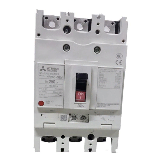
NF250-SEV with MDU, NF250-HEV with MDU
NF400-SEW with MDU, NF400-HEW with MDU
NF800-SEW with MDU, NF800-HEW with MDU
INSTRUCTION MANUAL
● Read this Instruction Manual carefully prior to use, so that the product is used properly.
● After reading this manual, store it in a safe place so that it can be easily referenced when needed.
● Make sure that the end user receives this Instruction Manual.
Indications and what they mean are listed below.
Danger
Caution
MDU Breaker main unit
Securely insert the connection cable into the MDU connector (until the lock clicks into place). The product will be unable to measure
properly if the connection is poor.
Some models/specifications do not measure or display some items. These items and functions will be skipped.
For models with CC-Link communication, refer to the PLC User
• CC-Link System Master/Local Module User
* The CC-Link version is
Wrong handling may cause dangerous situation in which possibility of fatal accidents or serious injuries assumed.
Wrong handling may cause dangerous situation in which possibility of significant or minor injuries, or material damages assumed.
Using this under certain conditions may cause electrical shock.
s Manual
'
CC-Link Ver. 1.10.
"
"
Caution
Connection cable
s Manual before reading this Instruction Manual.
'
Connector
MDU
Advertisement
Table of Contents

Related Manuals for Mitsubishi Electric MDU-BN


Summary of Contents for Mitsubishi Electric MDU-BN
- Page 1 MDU BREAKER: MDU TYPE MDU-BN, MDU-BP, MDU-BC, MDU-BM MODEL NF250-SEV with MDU, NF250-HEV with MDU NF400-SEW with MDU, NF400-HEW with MDU NF800-SEW with MDU, NF800-HEW with MDU INSTRUCTION MANUAL ● Read this Instruction Manual carefully prior to use, so that the product is used properly.
-
Page 2: Table Of Contents
■ Table of Contents ………………………………………………………………………………………………………… 1. Safety Precautions ………………………………………………………………………………………………………… 2. Precautions for Use ……………………………………………………………………………………… 2.1 Standard operating conditions ………………………………………………………………………………………………… 2.2 Withstand voltage test ………………………………………………………………………………………… 2.3 Connection and installation ………………………………………………………………………………………………………………… 2.4 Requests ………………………………………………………………………………………………………… 2.5 Notes on usage …………………………………………………………………………………… 3. MDU Breaker Installation Instructions ……………………………………………………………... - Page 3 ………………………………………………………………………………… 5. Names and Functions of MDU Parts …………………………………………………………………………………………… 5.1 Display/operation panel ……………………………………………………………………………………… 5.2 MDU terminal block section ………………………………………………… 5.3 CC-Link setting area (with CC-Link communication option) ………………………………… 5.4 Number of CC-Link communication connectable units and precautions ………………………………………… 5.5 Installation and wiring for products with CC-Link communication ……………………………………………………………………………………...
-
Page 4: Safety Precautions
1. Safety Precautions This Instruction Manual is meant mainly for those with specialized electrical knowledge who will use this product to manufacture assembled products, perform electrical work, or conduct maintenance and inspections. This also includes those who will operate this product (the end user). Caution ●... -
Page 5: Withstand Voltage Test
2.2 Withstand voltage test Caution ● When conducting a MDU terminal test, always connect the MDU Breaker main unit and MDU. ● A voltage measurement transformer is connected between poles on the load side of the MDU Breaker main unit. In the table below, ×... -
Page 6: Connection And Installation
2.3 Connection and installation Caution ● MDU Breaker cannot be used with the power side and load side reversed. ● Do not forcefully pull the connection cable between the MDU and MDU Breaker main unit (15 N or less). Doing so may loosen or disconnect the cable. -
Page 7: Requests
(2) Mitsubishi Electric shall not be held responsible for damage caused for reasons not attributable to Mitsubishi Electric; opportunities or profit lost by customers caused by Mitsubishi Electric product failure; damage caused from extraordinary circumstances, secondary damage, accident compensation, damage to anything other than Mitsubishi Electric products, or compensation for any other work, whether foreseen or not by Mitsubishi Electric. -
Page 8: Mdu Breaker Installation Instructions
3. MDU Breaker Installation Instructions Caution ● When mounting or removing the MDU, first turn the host circuit breaker OFF and confirm that no electricity is flowing. ● First set the MDU Breaker main unit to OFF or TRIP, and then mount the MDU and connection cable. 3.1 MDU Mounting (external mounting for 250 A frame) 3.1.1 Check the wiring of the connection cable (1) Check that the connection cable is drawn out through the cable outlet port of the MDU Breaker without catching. -
Page 9: Mounting Of Mdu To Mdu Breaker Main Unit
3.1.3 Mounting of MDU to MDU Breaker main unit (1) Ground (class D) the FG terminal on the MDU mounting plate. (2) Securely insert the connection cable coming out from the MDU Breaker main unit into the MDU connector (until the lock clicks into place). (Figure 4) <Connecting the connector>... -
Page 10: Mdu Mounting (External Mounting For 400/800 A Frame)
3.2 MDU mounting (external mounting for 400/800 A frame) 3.2.1 Mounting of MDU mounting plate (1) Screw the MDU mounting plate into the MDU Breaker main unit. (Figures 9, 10) Use the included “ M4 × 8 ” screws. Caution Make sure that the connection cable is not caught and damaged between the MDU mounting plate and MDU. -
Page 11: Mounting Of Mdu To Mdu Breaker Main Unit
3.2.2 Mounting of MDU to MDU Breaker main unit (1) Ground (class D) the FG terminal on the MDU mounting plate. (2) Securely insert the connection cable coming out from the MDU Breaker main unit into the MDU connector (until the lock clicks into place). (Figure 11) Caution Do not forcefully pull the connection cable. -
Page 12: Mdu Mounting (Panel Mounting)
3.3 MDU mounting (panel mounting) 3.3.1 No transmission, electric energy pulse output 1 Precautions for mounting Install with an amount of space left equal to the measurement on the right or higher. (Figure 17) MDU panel cutting dimensions (No transmission, with pulse output) Model 86.5 NF250-SEV... - Page 13 3 Connecting cable connection Securely insert the connection cable coming out from the MDU Breaker main unit into the MDU connector (until the lock clicks into place). (Figure 21) Caution Do not forcefully pull the connection cable. Doing so may result in a disconnection of the cable. <Connecting the connector>...
-
Page 14: With Cc-Link Communication/Modbus Communication
3.3.2 With CC-Link communication/MODBUS communication 1 Precautions for mounting Install with an amount of space left equal to the measurement on the right or higher. (Figure 23) (CC-Link/MODBUS) MDU panel cutting dimensions Model 86.5 NF250-SEV with MDU 250 A Caution frame NF250-HEV with MDU... -
Page 15: Wiring Of Mdu Terminal Block
4 Connecting cable connection Securely insert the connection cable coming out from the MDU Breaker main unit into the MDU connector (until the lock clicks into place). (3.3.1 Figure 21 on page 12.) <Binding the cable> Caution Do not forcefully pull the connection Binding band cable. - Page 16 [Wiring for products with electric energy pulse output] Caution ● The 114 and 113 pulse output terminals are included with MDUs with electric energy pulse output. ● The pulse output line forms a small-signal circuit. Install it at least 10 cm away from strong circuits. The wiring length is determined by various conditions such as the anti-noise performance of the pulse receiver.
-
Page 17: Mdu Features And Functions
4. MDU Features and Functions 4.1 Features of MDU ● The load current, line voltage, harmonic current (fundamental frequency; 3rd, 5th, 7th, 9th, 11th, 13th, 15th, 17th, and 19th order; and total), electric power, reactive power, electric energy, reactive energy, power factor, and frequency flowing to MDU Breaker can be measured and displayed. ●... -
Page 18: Measurement Functions
4.3 Measurement functions 4.3.1 Measurement function list The following table lists measurement elements and elements that can be communicated/displayed. Measurement elements that can be communicated and displayed. Measurement elements Communication Display Display rauge* ● ● Each-phase 0.0, 1.2 to 999.9, 1000 to 1600 A ●... -
Page 19: Measurement Rated Values/Measurement Range And Accuracy
4.3.2 Measurement rated values/measurement range and accuracy (1) Electric current [1] The present value is the effective value during a single cycle. [2] “ Each-phase ” means the 1-, 2-, 3-, and N-phase. [3] Totals (average value) are calculated as follows when setting the phase and wire (factory setting is three-phase three-wire for three-pole products, and three-phase four-wire for four-pole products). - Page 20 (2) Voltage [1] The present value is the effective value during a single cycle. [2] “ Between each line ” means the between phases, such as between 1-phase and 2-phase, 2-phase and 3-phase, 3-phase and 1-phase, 1-phase and N-phase, 2-phase and N-phase, and 3-phase and N-phase. [3] Totals (average value) are calculated as follows when setting the phase wire type.
- Page 21 (4) Electric energy/Reactive energy [1] The integrated value is the cumulative total value, from when usage began (after previous reset) to now. (The electric energy during reverse power flow is not added.) [2] The electric energy and reactive energy can be set to any value. [3] The latest one hour amount is the one hour amount from one hour to the next hour as measured by the internal clock.
- Page 22 (7) Harmonic current [1] The present value is the effective value during a single cycle. [2] The present harmonic current value measures the fundamental frequency and order (3rd, 5th, 7th, 9th, 11th, 13th, 15th, 17th, 19th) of each phase (1-phase, 2-phase, 3-phase, N-phase). [3] “...
-
Page 23: Monitoring Functions
4.4 Monitoring functions 4.4.1 Monitoring function list ● The following table shows monitoring elements, along with elements that can be displayed on the display or communicated. “ Display ” indicates that the item is displayed on the display. “ Communication ” indicates that the item can be communicated through CC-Link, MODBUS communication. -
Page 24: How To Use Monitoring Functions
4.5 How to use monitoring functions 4.5.1 MDU Breaker alarms (1) PAL (load current pre-alarm) The alarm is output to display/over communication when the load current ≥ the pre-alarm current, and the duration ≥ Alarm details the pre-alarm operation time (1/2 the long limit time operation time TL). Do not set it via communication or on the display. - Page 25 (4) ILA_AL (electric current open phase alarm) Monitoring starts when the load current for any phase reaches or exceeds 10% of the measurement rated current. Alarm details The alarm is output to display/over communication when an energization phase equal to or less than the maximum phase current ×...
-
Page 26: Mdu Breaker Status
4.5.2 MDU Breaker status Communicates the total number of times the MDU Breaker has tripped from when usage Trip frequency began to now. MDU Breaker status details Open/close Communicates the total number of times the MDU Breaker has opened/closed from when frequency usage began to now. -
Page 27: Network Specifications For Mdu
4.6 Network Specifications for MDU 4.6.1 Electric energy pulse output Item Specification Output elements Solid state relay (SSR), No voltage a contact (113 and 114 terminals: no polarity) Contact capacity Compatible with 24 VDC and 100 to 200 VAC, 20 mA Output pulse unit 1, 10, 100, 1000 and 10000 kWh/pulse (settable) Output pulse width... -
Page 28: Names And Functions Of Mdu Parts
5. Names and Functions of MDU Parts Some models do not measure or display (transmit) some items or functions. These items and functions will be skipped. * Refer to “ 7. MDU Operation Procedure ” for details. 5.1 Display/operation panel The display direction on the display can be changed. -
Page 29: Mdu Terminal Block Section
5.2 MDU terminal block section (1) Control power supply terminals: L1 and L2 Connect to the MDU control power supply. They have no polarity. (2) Ground terminal: FG (on mounting plate) MDU external mounting: FG terminal on mounting plate of MDU Breaker main unit MDU panel mounting: FG terminal on MDU mounting bracket Connect above terminals to class D ground. -
Page 30: Cc-Link Setting Area (With Cc-Link Communication Option)
5.3 CC-Link setting area (with CC-Link communication option) The MDU is a remote device station that occupies a single station. MDU input data is retained if a sequencer CPU error or data ring error occurs. (1) Station number (STATION No.) setting switches Open the cover for the setting area on the front of the MDU, and use the station number setting switches to set the CC-Link communication station number via BCD code. -
Page 31: Number Of Cc-Link Communication Connectable Units And Precautions
5.4 Number of CC-Link communication connectable units and precautions The MDU is a remote device station that occupies a single station. The number of connectable units and combinations with other devices must satisfy both “ number of connectable units in condition 1 ” and “ number of connectable units in condition 2 ” below. Number of connectable units in condition 1 {(1 ×... -
Page 32: Installation And Wiring For Products With Cc-Link Communication
5.5 Installation and wiring for products with CC-Link communication 5.5.1 Terminator installation Terminators (included with the master unit) must be installed on the units at both ends of the CC-Link transmission line. Master unit Terminator Special CC-Link Special CC-Link cable cable If the MDU is at the end of the CC-Link transmission line, connect a terminator between DA and DB in the MDU terminal block. -
Page 33: Modbus Setting Area (With Modbus Communication Option)
5.6 MODBUS setting area (with MODBUS communication option) (1) MODBUS address setting switches These switches are used to set the addresses for MODBUS communication. (Factory setting: ON, EVEN) ADDRESS Set the addresses so that there are no duplicate ones set on the same transmission route. 64 32 16 8 4 2 1 Setting example: Values of the switch when turned ON are 16 and 1. -
Page 34: Installation And Wiring For Products With Modbus Communication
5.7 Installation and wiring for products with MODBUS communication (1) Connection of termination resistor Master Unit MDU Unit MDU Unit A termination resistor must be connected to the unit at both ends of the MODBUS communication line. Since the MDU has built-in terminating resistors, it is possible to connect a terminating resistor by short-circuiting 485- and Ter terminal. -
Page 35: Mdu Detailed Specifications
6. MDU Detailed Specifications 6.1 Precautions for measurement (1) Electric current measurement accuracy The MDU electric current measurement accuracy is ± 1.0% of the maximum current setting (measurement rated current) of the circuit breaker. For example, the permissible difference of NF400-SEW with MDU is 4.0 A (400 A × 1.0%), so the permissible difference from a current of 0 A to 400 A would be ±... - Page 36 (4) Intermittent load (such as welder) measurement Items such as current, voltage, and electric power are measured (sampled) once every 250 ms. Any values, such as current value, are calculated and the measurement value is updated at this timing. However, the minimum update cycle for measurement results displayed on the display or output over communication data is 500 ms. This will result in a larger errors if there is a continuous load (such as due to a resistance welder), and is therefore not suited for measurement in such cases.
-
Page 37: Mdu Operation Procedure
7. MDU Operation Procedure Display items and functions are set using the selection switches [1] through [4] shown in the figure below. Settings are switched each time a switch is pressed. (For example, when setting the phase it will cycle from 1 → 2 → 3 → N → 1 and repeat.) The UP and DOWN switches ([6]) can be used to set a numerical value for the selected item or when there are further items to select. -
Page 38: Operating Method For Main Menu Screen
7.1 Operating method for main menu screen The main menu screen provides access to each display screen. Use the UP/DOWN switches to select a screen to display/set, and then press ENTER to switch to the selected screen. * Text will be inverted (black background and white text) when selected. [Main menu screen] Select this to display and configure protection characteristics. -
Page 39: Display Method For Protection Characteristic Setting Values
7.1.1 Display method for protection characteristic setting values • Select PROTECT from the main menu screen and press ENTER to switch to the protection characteristics selection screen. • Switches through LTD ⇔ STD/INST ⇔ ER ⇔ LTD..* Protection characteristics cannot be set (changed). Use the setting dials on the MDU Breaker main unit to change them. [Protection characteristics [Main menu screen] selection screen]... -
Page 40: Protection Characteristic Setting And Setting Method For 400/800 A Frame
(3) Rated Sensitivity Current I Δ n, Maximum Operating Time Te Check * No fuse breaker will be displayed as “ - ” . [Earth leakage characteristics ER setting value display screen] PROTECT t ON MENU t OFF I ⊿ n and Te setting values ●... -
Page 41: Method For Various Settings
(3) Rated Sensitivity Current I Δ n, Maximum Operating Time Te Check * No fuse breaker will be displayed as “ - ” . [Earth leakage characteristics ER setting value display screen] PROTECT t ON MENU t OFF I ⊿ n and Te setting values ●... - Page 42 (2) Line system setting [Default value: 3P3W] (3P4W for four-pole products) • Select LINE_S on the measurement setting selection screen. (Screen [1]) • Press ENTER to switch to the line system display screen. This allows the line system setting value to be changed. (Screen [2]) 1P2W (single-phase two-wire) 1P3W (single-phase three-wire) 3P3W (three-phase three-wire)
-
Page 43: Setting Method For Alarms
7.1.2-2 Setting method for alarms • Select ALARM from the setting item selection screen and press ENTER to switch to the alarm setting selection screen. • Switches through PAL ⇔ IDM_AL ⇔ ILA_AL ⇔ IUB_AL ⇔ AL_HOLD ⇔ PAL..[Alarm setting ●... - Page 44 (3) Electric current open phase alarm (ILA_AL) setting • Select ILA_AL on the alarm setting selection screen. (Screen [1]) • Press ENTER to switch to the electric current open phase alarm setting display screen. (Screen [2]) Select ON (function enabled) or OFF (function disabled) and press ENTER to decide the setting. •...
-
Page 45: Setting Method For Lcd
7.1.2-3 Setting method for LCD • Select LCD from the setting item selection screen and press ENTER to switch to the LCD setting selection screen. • Switches through BACK_L ⇔ CTRST ⇔ BRT_W ⇔ BRT_R ⇔ VIEW ⇔ REV_B/W ⇔ AL_BL ⇔ BACK_L..[Setting item selection screen] [LCD setting selection screen] Select with UP/DOWN... - Page 46 (4) Red brightness setting [Default value: 4 (center value of 1 to 7)] • Select BRT_R on the LCD setting selection screen. (Screen [1]) • Press ENTER to switch to the red brightness setting display screen. (Screen [2]) Use UP/DOWN to switch the red brightness of the screen. Press ENTER to decide the setting. •...
-
Page 47: Setting Method For Date And Time
(7) Backlight display during alarm setting [Default value: LIGHT (ON)] • Select AL_BL on the LCD setting selection screen. (Screen [1]) • Press ENTER to switch to the backlight display during alarm screen. (Screen [2]) ● LIGHT : ON Setting value switches through LIGHT ⇔ BLINK ⇔ LIGHT..Press ENTER to decide ●... -
Page 48: Setting Method For Electric Energy
7.1.2-5 Setting method for electric energy • Select EP/EQ from the setting item selection screen and press ENTER to switch to the ● EP : Electric energy setting electric energy setting selection screen. ● EQ : Reactive energy setting Switches from EP ⇔ EQ ⇔ EP..[Electric energy setting [Setting item selection screen] selection screen]... -
Page 49: Setting Method For Measurement Items
7.1.2-6 Setting method for measurement items • Select ITEM_S from the setting item selection screen and press ENTER to switch to the measurement item selection screen. • Switches through I ⇔ V ⇔ P ⇔ Q ⇔ EP ⇔ EQ ⇔ PF ⇔ Hz ⇔ HI ( A ) ⇔ HI ( % ) ⇔ FREE ⇔ SEQ_CHK ⇔ I ..[Measurement item [Setting item selection screen] selection screen]... -
Page 50: Setting Method For Free Display
7.1.2-7 Setting method for free display • Select FREE_S from the setting item selection screen and press ENTER to switch to the free display setting selection screen. • Switches through 1/4P_L ⇔ 1/4P_R ⇔ 2/4P_L ⇔ 2/4P_R ⇔ 3/4P_L ⇔ 3/4P_R ⇔ 4/4P_L ⇔ 4/4P_R ⇔ 1/4P_L..The display pattern can be freely changed to suit the application. -
Page 51: Method For Resetting Alarms
7.1.3 Method for resetting alarms • Select AL_RST from the main menu screen and press ENTER to display the allow changes screen. • Select YES and press ENTER to reset alarms. [Main menu screen] [Allow changes screen] PROTEC AL_RST SETTING ENTER ENTER AL_RST... -
Page 52: Method For Displaying Information Screen
7.1.5 Method for displaying information screen • Select INFO from the main menu screen and press ENTER to switch to the setting item display screen. • Switches through MODEL ⇔ PROTECT ⇔ ALARM ⇔ MEASURE ⇔ MODEL..• Select an item and press ENTER to confirm the setting for each item. [Main menu screen] PROTECT SETTING... -
Page 53: Operating Method For Measurement Display Screen
7.2 Operating method for measurement display screen 7.2.1 Switching method for display screen • Press MENU to switch between the main menu screen and measurement display screen. The measurement display screen can be displayed from any screen by holding MENU for two seconds. [Main menu screen] [Measurement display screen] [ V ]... -
Page 54: Measurement Display List
7.2.2 Measurement display list (1) Horizontal display [Demand value/ [Present value] [Demand value/present value] [Demand value/maximum value] all-phase maximum value] [ A ] [ A ] [ A ] [ A ] DT= 3min DT= 3min DT= 3min 340.0 1 7 / 0 1 / 0 1 0 0 : 2 5 ITEM PHASE... - Page 55 ..[Present value/total value] [Present value/1st order] [Demand value] [ A ] [ A ] [ A ] [ A ] DT= 3min To t a l 1s t 19 t h ITEM PHASE VALUE ITEM PHASE VALUE ITEM PHASE VALUE ITEM PHASE VALUE...
- Page 56 (2) Vertical display (view setting H-VIEW1) [Latest one [One hour amount [Present value] [Integrated value] hour amount] maximum value] [ A ] [ k W h ] [ k W h ] [ k W h ] 2000 1 7 / 0 1 / 0 1 0 0 : 0 0 VALUE CURRENT...
- Page 57 [Fault cause/ ..[Present value/ [Present value/ [Present value/ current display screen] total value] 1st order] 19th order] Without fault record [ A ] [ A ] [ A ] [ -] 1s t 19 t h To t a l T R I P VALUE VALUE...
-
Page 58: Fault/Alarm Display Details
7.2.3 Fault/alarm display details [Fault cause/current display screen] [Fault cause/current display screen] With fault records Without fault records [ A ] [ -] T R I P T R I P Fault cause 11328 I N S T Overload/short trip : Long time delay trip STD : Short time delay trip ITEM... -
Page 59: Appendix
8. Appendix 8.1 Precautions for setting operation The display can be used to set and clear the items described in “ 7.1.2 Method for various settings, ” “ 7.1.3 Method for resetting alarms, ” and “ 7.1.4 Method for resetting fault cause/current, maximum value, electric energy, and reactive energy. ” When items are set or cleared, the non-volatile memory storage will be overwritten for all of these except for the items described in “... -
Page 60: Communication Error Codes And Solutions
8.3 Communication error codes and solutions (1) With CC-Link transmission option Error code Note: The numbers in parentheses are in hexadecimal notation. Error details Solution Digital command, Standard command analog command, between devices or pulse command 1 (01h) Undefined command. Set the correct command. - Page 61 +880-31-624-307 +880-28-321-791 +855-23-997-725 +56-32-2-320-600 +86-21-2322-3030 +86-755-2399-8272 +86-28-8446-8030 +57-4-4441284 +20-2-27961337 +30-211-1206-900 +91-124-4630300 +62-(0)21-6610651-9 +856-20-415899 +356(0)21-697-816 +95-(0)1-202589 +977-1-4411330 +47(0)55-506000 +92-(0)42-35752323 +92-(0)42-35753373 +92-(0)42-37631632 +63-(0)2-634-8691 +966-1-4770149 +65-6473-2308 +34(0)93-565-3131 +58-212-241-9952 +84-28-3910-5945 +84-24-3937-8075...
- Page 62 MEMO...
- Page 64 MDU Breakers Nov 2019 LN107A330H02 IB63E30-A 1911 ( MEE)...
Need help?
Do you have a question about the MDU-BN and is the answer not in the manual?
Questions and answers