
Related Manuals for Crestron DigitalMedia 8G+ DM-RMC-4K-100-C-1G


Summary of Contents for Crestron DigitalMedia 8G+ DM-RMC-4K-100-C-1G
- Page 1 DM-RMC-4K-100-C-1G Wall Plate 4K DigitalMedia 8G+ ® Receiver and Room Controller 100 Supplemental Guide Crestron Electronics, Inc.
- Page 2 HDMI Licensing LLC in the United States and/or other countries. Other trademarks, registered trademarks, and trade names may be used in this document to refer to either the entities claiming the marks and names or their products. Crestron disclaims any proprietary interest in the marks and names of others.
-
Page 3: Table Of Contents
Contents Introduction Physical Description Front Panel......................2 Rear Panel ......................3 Communication with a Control System HDCP 2.2 Compliance Troubleshooting Appendix: Pin Assignments Contents • i Supplemental Guide – DOC. 7725A... -
Page 5: Introduction
® standard, allowing it to be connected directly to an HDBaseT certified source. For additional information about the DM-RMC-4K-100-C-1G, refer to the DM-RMC-4K-100-C-1G DO Guide (Doc. 7707) at www.crestron.com/manuals. This guide provides information about the following: • Physical description of the front and rear panels of the DM-RMC-4K-100-C-1G •... -
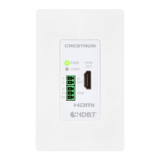
Page 6: Physical Description
DM-TX-4K-100-C-1G; however, video will pass through properly. The IR OUT and COM ports are supported only when the DM-RMC-4K-100-C-1G connects to an Ethernet-enabled DigitalMedia™ transmitter or switcher that is addressable from a Crestron control system. When the DM-RMC-4K-100-C-1G connects to a DigitalMedia switcher, the switcher must be in Private Network Mode (PNM). -
Page 7: Rear Panel
Connects to the DM 8G+ output of a DM switcher, transmitter, or other DM device, or ® to an HDBaseT device via CAT5e, Crestron DM-CBL-8G, or Crestron DM-CBL-ULTRA cable; Green LED indicates DM link status; Solid amber LED indicates HDCP video;... -
Page 8: Communication With A Control System
Communication with a Control System Unlike most DigitalMedia endpoints, the DM-RMC-4K-100-C-1G does not support an Ethernet-based CIP connection with a control system. In order to communicate with a control system, the DM-RMC-4K-100-C-1G must connect to a DigitalMedia switcher or transmitter that supports a CIP connection with the control system. The DigitalMedia switcher or transmitter communicates with the DM-RMC-4K-100-C-1G via a serial communications path in the DigitalMedia link. -
Page 9: Troubleshooting
Troubleshooting The following table provides troubleshooting information. If further assistance is required, contact a Crestron customer service representative. DM-RMC-4K-100-C-1G Troubleshooting TROUBLE POSSIBLE CAUSE(S) CORRECTIVE ACTION The video is not being The HDCP settings of one or more Ensure that the HDCP... -
Page 10: Appendix: Pin Assignments
Appendix: Pin Assignments This section provides information about pin designations and wiring for the following DM-RMC-4K-100-C-1G connectors: • DM IN • 24 V 0.75A to Power Pack DM IN Wiring Pin 1 WIRE WIRE Pin 8 NUMBER COLOR NUMBER COLOR Orange/White 5 Blue/White Orange... - Page 11 This page is intentionally left blank. DM-RMC-4K-100-C-1G: Wall Plate 4K DigitalMedia 8G+ Receiver • 7 Supplemental Guide – DOC. 7725A...
- Page 12 Crestron Electronics, Inc. Supplemental Guide – DOC. 7725A 15 Volvo Drive Rockleigh, NJ 07647 (2047536) Tel: 888.CRESTRON 10.16 Fax: 201.767.7576 Specifications subject to www.crestron.com change without notice.
Need help?
Do you have a question about the DigitalMedia 8G+ DM-RMC-4K-100-C-1G and is the answer not in the manual?
Questions and answers