Table of Contents
Advertisement
Quick Links
Setup Manual
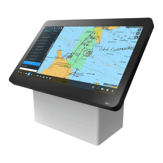
Touch Panel Color LCD Monitor
Important
Please read this "Setup Manual", and "User's Manual" (separate
volume) carefully to familiarize yourself with safe and effective
usage.
Please retain this manual for future reference.
• For monitor adjustment and settings, refer to the "User's Manual".
• For the latest product information including the "Setup Manual",
refer to our web site :
www.eizoglobal.com
Advertisement
Table of Contents

Related Manuals for Eizo DuraVision MDU5501WT


Summary of Contents for Eizo DuraVision MDU5501WT
- Page 1 Setup Manual Touch Panel Color LCD Monitor Important Please read this “Setup Manual”, and “User’s Manual” (separate volume) carefully to familiarize yourself with safe and effective usage. Please retain this manual for future reference. • For monitor adjustment and settings, refer to the “User’s Manual”. •...
- Page 2 EIZO Corporation is under no obligation to hold any submitted material or information confidential unless prior arrangements are made pursuant to EIZO Corporation’s receipt of said information. Although every effort has been made to ensure that this manual provides up-to-date information, please note that EIZO monitor specifications are subject to change without notice.
-
Page 3: Precautions
WARNING If the unit begins to emit smoke, smells like something is burning, or makes strange noises, disconnect all power connections immediately and contact your local EIZO representative for advice. Attempting to use a malfunctioning unit may result in fire, electric shock, or equipment damage. - Page 4 WARNING Keep small objects or liquids away from the unit. Small objects accidentally falling through the ventilation slots into the cabinet or spillage into the cabinet may result in fire, electric shock, or equipment damage. If an object or liquid falls/ spills into the cabinet, block the power supply immediately.
- Page 5 WARNING Use the correct voltage. • The unit is designed for use with a specific voltage only. Connection to polarities and voltages other than those specified on the monitor or in this User’s Manual may cause fire, electric shock, or equipment damage. •...
- Page 6 CAUTION Handle with care when carrying the unit. Disconnect the power cord and cables when moving the unit. Moving the unit with the cord attached is dangerous. It may result in injury. Unpacking and transporting of this product should be carried out by four or more people.
-
Page 7: Table Of Contents
CONTENTS PRECAUTIONS ............3 CONTENTS ............. 7 Chapter 1 Introduction ........8 1-1. Package Contents ......... 8 1-2. EIZO LCD Utility Disk........8 ● Disk contents ........... 8 1-3. Controls and Functions ....... 9 ● Front / Back ............. 9 ●... -
Page 8: Chapter 1 Introduction
• Setup Manual (this manual) • Cleaning cloth • Stylus (touch pen) 1-2. EIZO LCD Utility Disk An "EIZO LCD Utility Disk" (CD-ROM) is provided with this product. The following table shows the disk contents: ● Disk contents The disk includes a touch panel software and user manuals. Refer to the Readme file on the disk for file access procedures. -
Page 9: Controls And Functions
Fans to cool the monitor. Operates when the product interior reaches a high temperature. 4. Buzzer Can be activated to emit warning beeps by system-side control. Note • For details on system-side control, contact your local EIZO representative. Chapter 1 Introduction... -
Page 10: Side Face
● Side face 5. Handle Handles for transportation button Enables or disables touch panel operation. The button lights up blue when touch panel operation is enabled. Note • There are two buttons. You can use either one of them according to the installation position of the monitor. - Page 11 12. USB upstream port Connect a USB cable to this port to: • Use the touch panel. • Control the monitor via USB. • Use USB hub function. 13. DisplayPort connector Inputs DisplayPort signal of a PC. 14. HDMI connector Inputs HDMI signal of a PC.
-
Page 12: Chapter 2 Installation / Connection
Chapter 2 Installation / Connection 2-1. Installation This product can be installed horizontally or vertically. (Allowable angle: 0° (horizontal) to 90° (vertical)) ● Installation example Installation example 1: Horizontal Installation example 2: Vertical Attention • When installing the monitor vertically, place it so that the cable connectors are located on the lower side. •... -
Page 13: Installation Requirements
● Installation requirements Rear view Unit: mm 400.0 400.0 1. Cooling fan 1. Cooling fan 200.0 200.0 2. Operation 2. Operation 7. Installation surface 3. Air intake area 6. Mounting tapped hole 4. Connector 5. Buzzer Name Installation requirements 1. Cooling fan •... - Page 14 ● Ensuring ventilation Ensure ventilation by following the explanation of the figures below: Air intake area Ensure that no objects are placed within 60 mm of the ventilation slot. Dimensions Unit: mm 1334 Ventilation slot Air exhaust area (cooling fan) Ensure that no objects are placed within 60 mm of the ventilation slots.
-
Page 15: Checking The Strength Of The Installation Location
● Checking the strength of the installation location The weight of this product is approximately 71.7 kg. Check the withstand loads of the installation location and fittings used. ● Checking the installation environment • When mounting the monitor on a wall, pay attention to lighting equipment, sprinklers, and sensors on the ceiling. -
Page 16: Outline Dimensions
● Outline Dimensions Unit: mm 1334.0 60.8 60.8 Display area Mounting holes M8 Minimum depth 12 mm Maximum depth 15 mm 200.0 200.0 Thread pitch 1.25 mm (10 holes) 400.0 400.0 Chapter 2 Installation / Connection... -
Page 17: Connection
2-2. Connection Attention • Confirm the operation and performance of the cables before using them. • Check the shapes of the connectors, and connect the cables. • After a connector with a securing screw is plugged in, tighten the screw of the connector to secure the coupling. •... - Page 18 Connect the monitor to a power supply. There are two options for connecting the monitor to a power supply. Carry out the connection according to the installation environment and conditions of use. • Using the DC power terminal block • Using the AC power connector Attention •...
- Page 19 3. Install the terminal block. Install the terminal block to the monitor main unit, and tighten the left and right clamp screws using a flat-head screwdriver with tip width of 2.5 mm (recommended torque: 0.2 N·m to 0.3 N·m). Terminal block Terminal block Flat-head screwdriver Tighten...
-
Page 20: Displaying The Screen
2-3. Displaying the Screen When using the AC power supply, make sure the AC main power switch is turned ON. (It is set to ON by factory default.) lights up green when the switch is ON. Press to turn on the monitor. The monitor operation buttons light up green. - Page 21 If an image does not appear, switch the input signal. Procedure 1. Press The connector name of the currently displayed signal appears at the bottom right of the screen. 2. Press to switch signals. 3. Press to apply the change. HDMI DisplayPort If an image does not appear even after switching input signals, refer to “4-1.
-
Page 22: Ecdis Setup
• ECDIS Color Tables Specifications • Monitor Control Commands Specifications For details, contact your local EIZO representative or visit our website (www.eizoglobal.com) to send us an inquiry. Monitor setting is required to display in compliance with ECDIS standards. For details, refer to the monitor User’s Manual (in the CD-ROM). -
Page 23: Chapter 3 Touch Panel Settings
Make sure the USB cable has been connected between the monitor and PC (see page 17). Setting the sensitivity Execute the application "TPOffset" found in the EIZO LCD Utility Disk (CD-ROM), and adjust the sensitivity of the touch panel. For details, refer to the TPOffset User’s Manual (in the CD-ROM). - Page 24 Running calibration Attention • If a "User Account Control" dialog box is displayed during operation, proceed according to the displayed instructions. 1. Open the Windows Control Panel. The method for opening the Control Panel differs depending on the OS. Windows 10 In the Start Menu, click "Control Panel"...
- Page 25 6. Click "Calibrate". A calibration screen with a white background is displayed. Attention • If using the monitor in a multiple monitor environment, select the monitor to be used for calibration from the "Display" pulldown menu and then click "Calibrate". 7.
-
Page 26: Using Dmt-Dd
3-3. Using DMT-DD When using the touch panel driver provided by EIZO (DMT-DD), set up the driver according to the following procedure: Connecting a USB cable Make sure the USB cable has been connected between the monitor and PC (see page 17). -
Page 27: How To Use The Stylus (Touch Pen)
3-5. How to Use the Stylus (Touch Pen) Configure the touch panel settings before using the stylus (see “Chapter 3 Touch Panel Settings” (page 23)). ● Turning the power on 1. Press the power button. The power lamp lights up green once. To turn the power off, press the power button again. -
Page 28: Charging
● Charging The stylus provided with this product is charged via USB. When the battery power is low, the power lamp lights up red when the power is turned on. Recharge using the accompanying USB charger. When charging, the power lamp lights up red. When charging is finished, the light turns to green. Example: USB charger (USB 2.0) -
Page 29: Replacing The Tip
● Replacing the tip When the tip is worn away or broken, it must be replaced. Attention • Do not use the stylus if the tip is broken or removed. Doing so may damage the monitor surface. Replacement procedure 1. Turn the tip counter clockwise and remove it. 2. - Page 30 Attention • When not using the stylus, place it in the stylus holder. If it is placed directly on the touch panel, it will be detected as a foreign object, disabling the touch panel automatically. • The stylus holder uses a strong magnet. Be careful of the following: - Do not bring magnetic storage media and electronic equipment close to the stylus holder.
-
Page 31: Chapter 4 Troubleshooting
Chapter 4 Troubleshooting 4-1. No Picture Problem Possible cause and remedy 1. No picture • Check whether the power cord is connected properly. • None of the operation buttons light up. • Turn the main power switch on. • Turn off the main power, and then turn it on again a few minutes later. -
Page 32: Touch Panel Problems
4-2. Touch Panel Problems Problem Possible cause and remedy 1. Touch is not working. • Touch panel operation may be disabled. Press the button to enable it. The button lights up blue. • Check that the monitor and PC are connected with a USB cable. •... - Page 33 Problem Possible cause and remedy 2. Cursor position is not correct. / • Connect the monitor to the PC with the cable indicated in the Setup Cursor jumps. Manual. The touch panel may not work correctly if a conversion adapter is used. •...
- Page 34 Problem Possible cause and remedy 5. Calibration does not work • Hold down for two seconds or more to perform touch panel correctly. sensitivity adjustment. Do not touch the touch panel until the message "Don't touch the panel. Calibrating..." disappears from the screen.
-
Page 35: Appendix
Appendix Supported Resolutions The monitor supports the following resolutions: √: Supported -: Not supported DisplayPort HDMI Vertical scan Resolution frequency (Hz) PinP PbyP PinP PbyP PinP PbyP screen screen screen 640 × 480 59.940 √ √ √ √ √ √ √... -
Page 36: Pin Configuration Of Connectors
Pin configuration of connectors ● DC power connector Connector 1 2 3 4 Manufacturer Monitor Connector Model Terminal Block Model PHOENIX CONTACT IC 2.5/4-STGF-5.08 MSTB 2.5/4-STF-5.08 Pin configuration Pin No. Signal DC +24 V DC +24 V ● RS232C port (D-Sub 9-pin (female)) Connector Pin configuration Pin No. -
Page 37: Rs485 Port
● RS485 port Connector 1 2 3 4 5 6 7 8 Manufacturer Monitor Connector Model Terminal Block Model PHOENIX CONTACT MSTB 2.5/8-GF-5.08 FKCN 2.5/8-STF-5.08 Pin configuration Pin No. Signal Pin No. Signal TX_485_P RX_485_P TX_485_N RX_485_N TX_COM RX_COM TX_SHIELD RX_SHIELD Appendix... -
Page 38: How To Replace The Cooling Fan
How to replace the cooling fan Attention • Be sure to follow the procedure when replacing the fan. Note that EIZO Corporation assumes no responsibility for any damage caused due to incorrect handling of this product. Note • Please contact your local EIZO representative for replacement parts. - Page 39 Remove the fan from the fan holder. Screw M3 × 20 (four pcs) Label surface Tapped holes (four holes) Fan holder 1. Remove the screws (four pcs) that secure the fan. Use a Phillips screwdriver to remove the screws. 2. Remove the fan. Install a new fan in the fan holder.
-
Page 40: Periodic Check Of Buzzer Alarm
• The buzzer installed in this monitor can be activated to emit warning beeps by system-side control. • Check periodically to ensure that the warning beeps of the buzzer work. Use system-side control to check the buzzer. Note • For details on system-side control, contact your local EIZO representative. Appendix... - Page 41 Belgrader Straße 2, 41069 Mönchengladbach, Germany 〒 924-8566 石川県白山市下柏野町 153 番地 中国苏州市苏州工业园区展业路 8 号中新科技工业坊 5B 153 Shimokashiwano, Hakusan, Ishikawa 924-8566 Japan www.eizo.co.jp 00N0N199A1 www.eizoglobal.com SUM-MDU5501WT-AL Copyright © 2021 EIZO Corporation. All rights reserved 1st Edition - May, 2021 Printed in Japan.
Need help?
Do you have a question about the DuraVision MDU5501WT and is the answer not in the manual?
Questions and answers