
Subscribe to Our Youtube Channel
Related Manuals for Vixen AP Equatorial Mount


Summary of Contents for Vixen AP Equatorial Mount
- Page 1 Instruction Manual for AP Equatorial Mount / AP-SM Equatorial Mount / AP Photo Guider...
-
Page 2: Safety Precautions
PREFACE Thank you for your purchase of a Vixen product from the Vixen AP series of equatorial mounts and equatorial platform. This instruc- tion manual is prepared in common with the AP series of the equatorial mounts including the AP-SM equatorial mount and AP Photo Guider. -
Page 3: Table Of Contents
TABLE OF CONTENTS Page APPLICATION SAFETY PRECAUTIONS ---------------------------------------- P 2 : Polar Alignment Scope --------------------------------------- P34 TABLE OF CONTENTS ------------------------------------------- P 3 : Polar Alignment in the Northern Hemisphere -------------- P36 : Polar Alignment in the Southern Hemisphere ------------- P41 BEFORE USE ----------------------------------------------------- P 4 : Mount Menu --------------------------------------------------- P47 AP Mount... -
Page 4: Before Use
Basic Motion of the AP Equatorial Mount The AP equatorial mount moves and stops with friction in the right ascension (R.A) and declination (DEC). Slew the telescope by hand to change the telescope’s direction. The AP-SM mount comes equipped with a drive motor on the R.A a xis and a manual slow motion control knob on the DEC axis. -
Page 5: Name Of Each Components
* Utilized as a power supply when the R.A motor module is attached. Mount Specifications Mount AP equatorial mount Slow Motion Control R.A: Wheel and worm gears full circle micro movement DEC: Wheel and worm gears full circle micro movement... -
Page 6: Check The Package Contents
BEFORE USE Check the Package Contents The AP Photo Guider package contains the items listed below. Check if all the items are included. ⑩ ⑤ ① ④ ③ ② ⑦ ⑧ ⑨ ⑥ Package consisting of: ① AP Photo Guider Equatorial Platform ②... -
Page 7: Name Of Each Components
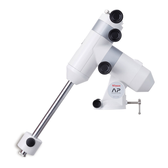
BEFORE USE Name of Each Component AP Photo Guider AP Photo Guider Equatorial Platform AP Mount Head Unit R.A Motor Module R.A Axis (Polar Axis) R.A. Clamp Lever 1/4” Camera Mounting Screw (4 points) Dovetail Slide Bar PG Safety Screw Polar Axis Cap (for Polar Scope) Dovetail Plate Lock Screw Polar Alignment Scope PF-L (Inside) -
Page 8: Mount & Cotroller Specifications
USB Micro-B (DC4.4 to 5.26V) Power Supply USB External battery pack (Not sold by Vixen) About 4 hours (at 20 degree C, with Alkaline batteries, 6kg loading weight ), 2.5 hours if the DEC motor module is used Working Duration with Batteries together. - Page 9 BEFORE USE Check the Package Contents AP-SM Mount The AP-SM equatorial mount package contains the items listed below. Check if all the items are included. ⑧ ① ② ③ ⑪ ⑥ ④ ⑨ ⑩ ⑤ ⑦ Package consisting of: ① AP-SM Equatorial Mount (Main body) ②...
-
Page 10: Ap-Sm Mount
BEFORE USE Name of Each Component AP-SM Mount DEC Axis Safety Screw Dovetail Plate Lock Screw Mount Head R.A Axis (Polar Axis) DEC Manual Slow Motion Control Knob Polar Scope Window Declination Body Cover Accessory Shoe Vanity Ring for Counterweight Bar Polar Axis Cap (for Polar Scope) R.A Motor Polar Alignment Scope PF-L... -
Page 11: Mount & Cotroller Specifications
USB Micro-B (DC4.4 to 5.26V) Power Supply 4 x AA batteries (Alkaline or Ni-MH, Ni-Cd rechargeable batteries), External USB battery pack (Not sold by Vixen) Working Duration with About 4 hours (at 20 degree C, with Alkaline batteries, 6kg loading weight ), 2.5 hours if the Batteries DEC motor module is used together. - Page 12 BEFORE USE Mount Specifications Mount Head The mounting block is designed to attach an optical tube with dovetail Mount head tube plate (or dovetsail slide bar). The optical tube is firmly fixed with Dovetail-plate tube plate both the lock screw with large grab knob and safety screw. This allows quick set up and removal of the optical tube.
- Page 13 BEFORE USE Friction Stop Mechanism The AP mount employs a friction stop mechanism which allows you DEC axis to move the optical tube by hand so that you can quickly point it at North your target celestial object The optical tube moves as you guide it by hand and stops as you release.
-
Page 14: Components Guide
BEFORE USE STAR BOOK ONE Components Guide Note: Usage of the STAR BOOK ONE is described as operating Instructions for the AP-SM Mount here. (10) Eyelet (10) Star Patent Pending DC12V Max.0.5A LCD Monitor N x999 (4) RA Reverse button (1) Mount button (6) Plus and Minus buttons (2) Display button... -
Page 15: Preparation
PREPARATION Assembling the Mount Refer to the instruction manual of your telescope and accessory together with this manual when you attach the optical tube assembly to the mount. The unit includes heavy items. Take care not to drop them when assembling as it could cause seriously damage the equipment or lead to injury. Take care not to pinch your finger with moveable pieces when setting up. - Page 16 PREPARATION Attach the metal post on the t r ipod head. The metal post is underneath the center column. Be sure to screw down the metal post completely Post Post Loosen the azimuth adjustment screws in advance by turning the a zimuth adjus tment knobs on the mount base Azimuth adjustment screw so that a space is opened for the metal post between the screws.
- Page 17 PREPARATION Tighten the azimuth adjustmen t knobs on the moun t base so that the two knobs are equally tightened. Azimuth adjustment screws Push down the leg brace until it clicks as to secure the stability of the tripod. Tighten the leg brace lock screw securely.
-
Page 18: Attaching The Counterweight
PREPARATION Attaching the Counterweight Be sure to attach the counterweight before you install the optical tube assembly on the mount. Screw the counterweight bar into the vanity ring until it is snug. Then, turn it back by one roation. Vanity ring for Counterweight bar Counterweight bar Screw down the counterweight bar into the declination body fully and tighten the vanity ring securely. -
Page 19: Attaching The Optical Tube Assembly
PREPARATION Attaching the Optical Tube Assembly The telerscope tube attaches to the AP mount via a dovetail tube plate. The permissible loading weight of the mount is 6kg (13.2 lbs). Dovetail tube plate Dovetail Slide bar Caution: Take care not to drop the telescope tube as it could result in serious damage. Loosen both dovetail plate lock screw and safety screw on the mount head fully so that space... -
Page 20: Attaching The Dovetail Slide Bar (Ap Photo Guider)
PREPARATION Attaching the Dovetail Slide Bar AP Photo Guider Loosen both the dovetail plate lock screw and safety screw on the mount head fully so that space is available for the dovetail slide bar. Dovetail plate Safety screw lock screw Back off Attach the dovetail slide bar to the mount head so that the dovetail slide bar fits securely into the sunken mount head. -
Page 21: Balancing The Equatorial Mount
Balancing the Equatorial Mount The Vixen AP is a German equatorial mount, in which the rotating R.A axis and rotating DEC axis cross each other at a right angle. The axes are rotated by using the movement of both axes to get maximum stability and limit the stress on the gears. If the equatorial mount is in an unbalanced state, it will increase stress to the gears and this could result in larger consumption of electricity or erratic operation. - Page 22 PREPARATION Second Step: Balancing the Mount in Declination (DEC) This should be done after you finish balancing in the R.A. In case of a telescope tube with tube rings: While holding the telescope tube, turn the counterweight bar (or telescope tube) by hand until the counterweight bar is horizontal.
- Page 23 PREPARATION Using a telescope tube with dovetail slide bar: This should be done after you finish balancing in the R.A. While holding the telescope tube, turn the counterweight bar (or telescope tube) by hand until the counterweight bar is horizontal. The declination body keeps the mount in position.
- Page 24 PREPARATION Tips on Proper Balancing The balance arrangements below illustrate various possible settings dependent on the length and weight of your optical tube. The center of gravity of the telescope is given as 25cm (10”) from the intersection of the R.A and DEC axes. Guidance 2...
-
Page 25: Connecting The Star Book One
PREPARATION Connecting the STAR BOOK ONE The AP-SM mount package comes equipped with an RA motor module and STAR BOOK ONE controller as standard accessories. Plug one end of the STAR BOOK cable into the connection port on the mount. Controller cable end Secure the connectors with the fixing screws. -
Page 26: About Power Supply
PREPARATION About Power Supply The AP-SM mount runs on self-contained four (4) AA –size batteries, or a USB external battery. The AC Adapter 12V-3A for SX mount is not available for the AP-SM mount. Installing AA-size Batteries The AA –size alkaline batteries or Ni-MH or Ni-Cd AA rechargeable batteries are recommended. Remove the battery compartment cover on the declination body. - Page 27 PREPARATION Using a USB External Power Supply Use a commercially available USB external battery with USB Micro-B connector. Note 1: The USB external battery will take priority over the AA batteries if you turn on the power while the AA batteries remain in the battery compartment.
-
Page 28: Initial Setting And Basic Operation
INITIAL SETTING AND BASIC OPERATION Turning ON the Power The power switch is located on the bottom of the R.A motor module if you have the AP-SM mount version. To turn on the power, press the side marked “I“on the switch, and to turn off the power, press the “O”... -
Page 29: Moving The Ap Mount
INITIAL SETTING AND BASIC OPERATION Basic Operation of the AP Equatorial Mount Moving the AP Mount The AP Mount is designed to move and stop the rotational axes without a clamp system. The tracking and slow motion control are done with the manual slow motion control knobs. -
Page 30: Changing Tension Of The Friction Stop Motion
INITIAL SETTING AND BASIC OPERATION Changing Tension of the Friction Stop Motion The tension of the friction stop motion can be adjusted in the R.A and DEC axes as the need arises. The position of each tension adjustment screw for the R.A and DEC axes is shown in the figure. Adjust the tension of the friction stop motion by loosening or tightening the tension adjustment screws with the supplied 4mm Allen wrench. -
Page 31: Approximate Polar Aligning With The Finder Scope
INITIAL SETTING AND BASIC OPERATION Approximate Polar Aligning with the Finder Scope After setting up the telescope, locate the AP mount so that its R.A axis points toward the nor th celestial pole. In this section an approximate Polar alignment using a finder scope is described for observers in the nor thern hemisphere. The finder scope on your telescope must be aligned accurately before you star t aligning the mount. - Page 32 INITIAL SETTING AND BASIC OPERATION Find Polaris from Cassiopeia and the Big Dipper A rough setting with a compass or pointing the polar axis of your telescope’s mount at Polaris will work well for visual observation. The constellations Cassiopeia and the Big Dipper (part of Ursa Major) are near Polaris. You will be able to find Polaris if you know the position of these groups of stars.
-
Page 33: Approximate Polar Aligning With The Polar Meter
INITIAL SETTING AND BASIC OPERATION Approximate Polar Aligning with the Polar Meter The Polar Meter is optional and it is not included in the AP Mount packages. Loosen the angle lock knob of the Polar Meter and tilt it to an angle that is equal to the altitude of Polaris at your location. Then, tighten the angle lock knob. -
Page 34: Application Polar Alignment Scope
APPLICATION Polar Alignment Scope If your intention is to take long exposure astrophotography, you must accurately align the polar axis (R.A) of the mount to the celestial pole. This requires the use of a polar alignment scope sold separately. The polar alignment scope can align the polar axis of the mount as accurately as 3 arc minutes or less. - Page 35 APPLICATION Replacing the Battery While holding the brightness adjusting dial by hand, remove the battery cover Battery cover (the switch for illuminator) on the top of the brightness adjusting dial by turning it counterclockwise. Turn the battery compartment on the polar alignment scope downward as shown in the figure so that the old Brightness adjusting dial...
-
Page 36: Polar Alignment In The Northern Hemisphere
Polar Alignment in the Northern Hemisphere The polar axis of the AP equatorial mount is aligned to the North Celestial Pole in the northern hemisphere. The polar alignment scope utilizes 3 stars of Polaris, Delta UMi and 51 Cep near the North Pole. Positions of the above stars are plotted on the reticle of the polar alignment scope. - Page 37 APPLICATION Open the round window on the declination body by sliding down the shutter of the window. While looking into the polar alignment scope, turn the polar alignment scope body so that the engraved Big Dipper (or Cassiopeia) on the reticle matches the Big Dipper (or Cassiopeia) in the real sky.
- Page 38 APPLICATION While looking into the eyepiece of the polar ★ Celestial north ★ Celestial north alignment scope, adjust the direction of the mount by turning the altitude adjustment bolt and azimuth adjustment knobs so that Polaris comes as close as possible to the designated position on the reticle.
- Page 39 Since there is no mark that points at the North Celestial Pole, you to the location of the year 2014 on the scale. And then, Polaris will need to match the polar axis of your AP equatorial mount with the get out of position from the gap between the lines.
- Page 40 APPLICATION While looking into the eyepiece of the polar ★ Celestial north ★ Celestial north alignment scope, turn the altitude adjustment bolt and azimuth adjustment knobs so that Polaris comes to the gap between the two segments of the lines marked 2014 and 2040.
-
Page 41: Polar Alignment In The Southern Hemisphere
Polar Alignment in the Southern Hemisphere The polar axis of the AP equatorial mount is aligned to the South Celestial Pole in the southern hemisphere. The polar alignment scope utilizes 3 stars of Sigma Octantis, Tau Octantis and Chi Octantis near the South Pole. Positions of these star are plotted on the reticle of the polar alignment scope. - Page 42 APPLICATION Open the round window on the declination body by sliding down the shutter of the window. While looking into the polar alignment scope, turn the polar alignment scope body so that the engraved Southern Cross (or Alpha Eridani) on the reticle directs the Southern Cross (or Alpha Eridani) in the real sky.
- Page 43 APPLICATION While looking into the eyepiece of the polar ★ Celestial south ★ Celestial south alignment scope, adjust the direction of the mount by turning the altitude adjustment bolt and azimuth adjustment knobs so that Sigma Octantis comes as close as possible to the designated position on the reticle.
- Page 44 APPLICATION Now, Sigma Octantis gets out of place from the designated position but it is not necessary to correct for it at this stage. Celestial south Celestial south Center of polar the alignment scope´s field of view (Center of the rotational axis of the equatorial mount) Since there is no mark that points at the South Celestial Pole, Turn the polar scope body so that Tau Octantis comes near you need to match the polar axis of your AXJ mount with the...
- Page 45 APPLICATION ★ Celestial south While looking into the eyepiece of the ★ Celestial south polar alignment scope, turn the altitude adjustment bolt and azimuth adjustment knobs so that Sigma Octantis comes to the gap between the two segments of the lines marked 2014 and 2040.
- Page 46 APPLICATION Tips on Finding Octans The constellation Octans is made up of dark stars about 5th magnitude on average. The nearest star to the south celestial pole is Sigma Octantis, which is one of four stars forming a trapezoid in Octans, visible at 5.5th magnitude. There are a few methods to locate inconspicuous Octans using the surrounding stars.
-
Page 47: Mount Menu
APPLICATION Change Settings on the Mount / Controller STAR BOOK ONE controller menus allow you to change your desired settings on the mount (and controller) Mount Menu Pressing the MOUNT button will turn up the brightness of the button itself and allow you to access various Mount menus using the direction keys. -
Page 48: Tracking Direction
APPLICATION Tracking Direction The slewing direction of a telescope differs in the nor thern and southern hemispheres. This allows for changing the rotation of the motors to slew the telescope correctly in your observing site. The setting is defaulted to the motion in the nor thern hemisphere “TrackDir N Hemis”. -
Page 49: Backlash Compensation
APPLICATION Backlash Compensation Backlash is a momentary stoppage of the tracking motion of the mount that occurs when the motor gears reverse their rotation. Backlash does not occur while the mount continues tracking at a constant speed as the gears keep contact with each other, however, it may occur when the telescope is slewed with different speeds. - Page 50 APPLICATION Press the Mount button to make the direction keys available. Confirm the amount of backlash in the direction of RA. Center the star in the field of view of your eyepiece and watch how the star moves while pressing the left direction key. Keep pressing the direction key until the star begins to move.
-
Page 51: Setting For Autoguider
APPLICATION Setting for Autoguider The STAR BOOK ONE can be used for auto guiding in conjunction with an external autoguiding system that is compatible with the SBIG autoguider. Available setting rates for compensating guide errors are described here. Auto guiding allows you to automatically guide a telescope on an equatorial mount by means of an autoguider, which translates signals from a CCD video camera attached on a guide scope, to achieve uniform and precise tracking speed of the mount. -
Page 52: Pec
APPLICATION PEC (Periodic Error Correction) Equatorial mounts with drive motors are designed to precisely track the motion of celestial objects. With the use of a telescope mounted on the equatorial mount, you may notice that stars in the field of view of the telescope at high magnification are drifting back and forth very slowly over a period of time (e.g. - Page 53 APPLICATION Stopping the PEC Recording Press the MOUNT or DISPLAY button to stop the PEC recording. The dialogue “PEC StopRec” appears on the display and press the + button to stop. Pressing the minus button will cancel the dialogue and continue the PEC recording. StopRec? If the PEC recording is stopped, only the ongoing record of the current cycle is cleared.
-
Page 54: Display Menu
APPLICATION Display Menu Pressing the DISP. button will turn up the brightness of the button itself and allows you to access various Display menus for setting with the direction keys. At the same time, it disables the direction keys for slewing the mount. Press the DISP. button again to return to slewing with the direction keys. -
Page 55: Red Led Light Adjustment
Reset All the settings for the mount and controller can be initialized to the defaulted settings at the Vixen Reset factory. To reset the settings, turn on the power while pressing the plus button and the red LED light button simultaneously for more than one second. -
Page 56: Ap Mount Composition Chart
APPLICATION Modules for the AP Mount The AP mount is composed of sectional modules and units. It can be easily rearranged or upgraded for your specific need. AP Mount Composition Chart AP Clamp Lever Manual Slow Motion AP Clamp Mount Head Unit AP Clamp Mount Head Unit Manual Slow Motion Control Module... -
Page 57: Variations On The Ap Mount
APPLICATION Variations on the AP Mount AP Mount with Single-Axis Motor Drive Manual Slow Motion Control Module AP Clamp Mount Head Unit Consisting of: AP Clamp Mount Head Unit AP Declination Body Unit R.A Motor Module Manual Slow Motion Control Module (w/ STAR BOOK ONE) Counterweight Bar Unit AP Polar Axis Body Unit... -
Page 58: How To Change The Modules
APPLICATION How to Change the Modules Remove the optical tube, counterweight bar and controller before changing modules. Take out the batteries from the battery compartment and disconnect the external power supply if it is used. Case 1: Changing the R.A. Motor Module for the Manual Slow Motion Control Module Remove the declination body cover. - Page 59 APPLICATION Turn the manual slow motion control module so that the screw holes Manual slow motion Manual slow motion control module control module (larger holes with no thread) are aligned in tandem. Replace the three socket head cap screws in place. Tighten the screws with the 3mm Allen wrench securely.
-
Page 60: Slow Motion Control Module
APPLICATION Case 2: Changing the Manual Slow Motion Control Module for the DEC. Motor Module. Remove the declination body cover. Declination body cover Declination body cover Open up the polar scope window on the declination body by sliding down the shutter. While pushing down on the hook on the bottom of the declination body, pull out the declination body cover by pinching the hook and window hole with fingers. - Page 61 APPLICATION Attach the declination body assembly onto the polar axis body assembly so that the electrical con- DEC motor module DEC motor module tact on the declination body fits snugly on the sunken portion on the manual slow motion control unit as shown in the figure.
- Page 62 APPLICATION Case 3: Changing the Manual Slow Motion Control Module for the R.A. Motor Module. Remove the declination body cover. Declination body cover Declination body cover Open up the polar scope window on the declination body by sliding down the shutter. While pushing down on the hook on the bottom of the declination body, pull out the declination body cover by pinching the hook and window hole as shown Window...
- Page 63 APPLICATION Turn the R.A motor module to change the orientation so that the R.A motor module R.A motor module screw holes (larger holes with no thread) are aligned in tandem. Re- Allen wrench Allen wrench place the the three socket head cap screws in place and tighten the screws securely with the 3mm Allen wrench.
-
Page 64: Upgrading The Ap Photo Guider To The Ap Mount
APPLICATION Upgrading the AP Photo Guider to the AP Mount with Dual-axis Motor Drive Necessary Parts (Optional) · AP Clamp Mount Head Unit 4mm Allen wrench 4mm Allen wrench · DEC Motor Module · AP Declination Body Unit Mount head unit Mount head unit ·... - Page 65 APPLICATION While holding the declination body, attach the declination body securely with the two supplied M5-25mm long screws using the 4mm 4mm Allen wrench 4mm Allen wrench Allen wrench. Attach the AP clamp mount head unit onto the DEC motor module Mount head unit Mount head unit with the electrical contact on the outside so that the central protruding...
- Page 66 APPLICATION While holding the DEC motor module, fix the declination body securely with the two supplied M5-25mm long screws using the 4mm Allen wrench. Install the batteries, if necessary. 4mm Allen wrench 4mm Allen wrench Replace the declination body cover with attention to the direction of the hook on the cover.
-
Page 67: Replacing The Fuse
APPLICATION About a Fuse Box In the AP mount, the electrical circuit board is protected by a fuse. It Specifications: is a rare case that a fuse is cut off in general use of the mount. If this 125V 1A Class-B (PES standard) happens, you will need to replace the fuse with a fresh one. -
Page 68: Specifications
SPECIFICATIONS Connector on the STAR BOOK ONE Patent Pending DC12V Max.0.5A 65mm(2. 56”) Controller cable connecting port(D-SUB9PIN male plug) Autoguider port Ra− Dec- Dec+ Ra+ GND NC Autoguider port Pin Layout R.A motor module power supply port External power supply port USB Micro-B(DC4.4~5.26V) Power switch Controller cable connecting port... -
Page 69: Dimensions
SPECIFICATIONS AP Mount Dimensions 274mm(10. 78”) 79mm(3. 11”) 80mm(3.15”) Fulcrum φ96mm(3.78”) φ 4 4. 8m m 112mm(4.41”) (1. 76”) R.A Motor Module Dimensions DEC Motor Module Dimensions φ78mm(3.07”) φ78mm(3. 07”) 52mm(2. 05”) 52mm(2. 05”) Electrical contact Electrical contact 80mm(3.15”) 51. 5mm(2. 03”) 80mm(3. - Page 70 SPECIFICATIONS Manual Slow Motion Control Module Dimensions Worm gear shaft 38. 5mm(1.52”) φ78mm(3.07”) φ78mm (3.07”) APP-TL130 Tripod Dimensions...
- Page 71 MEMO M e m o...
- Page 72 5-17-3 H i gash itokorozawa,Tokorozawa, S tama 359-0021, Japan P h o n e +81-4-2944-4141 ( International ) h t t p : / / w w w . v i x e n . c o . j p F a x +81-4-2944-9722 ( International ) (...
Need help?
Do you have a question about the AP Equatorial Mount and is the answer not in the manual?
Questions and answers