
Related Manuals for Inficon T-Guard2


Summary of Contents for Inficon T-Guard2
- Page 1 Translation of the original operating instructions T-Guard2 Leak Detector Catalog No. 540-200, 540-201 From software version jina85en1-13-(2009) V 2.41...
- Page 2 INFICON GmbH Bonner Strasse 498 50968 Cologne, Germany...
-
Page 3: Table Of Contents
INFICON Table of contents Table of contents 1 About this manual............................. 6 1.1 Target groups ............................ 6 1.2 Warnings.............................. 6 2 Safety ................................ 7 2.1 Intended use ............................. 7 2.1.1 Incorrect usage .......................... 7 2.2 Duties of the operator .......................... 7 2.3 Owner requirements .......................... 7 2.4 Dangers .............................. 9 3 Scope of delivery, transport, storage...................... 10... - Page 4 Table of contents INFICON 5.4 Connecting to the power supply system .................... 31 5.5 Connecting the PLC inputs to the electrical system ................ 32 5.6 Connecting the PLC inputs to the electrical system ................ 33 5.7 Connecting the analogue outputs to the electrical system .............. 35 5.8 Connecting to a PC.......................... 35...
- Page 5 INFICON Table of contents 7.1.2 Allocation of functions for PLC output.................. 61 7.1.3 Acumulation measurement using PLC.................. 64 7.1.4 Carrier gas measurement using PLC.................. 65 7.2 Controlling using RS-232........................ 66 7.3 Configuring analog outputs........................ 67 8 Save parameters ............................ 70 9 F.A.Q. - Frequently Asked Questions...................... 72 10 Warning and error messages ......................... 74...
-
Page 6: About This Manual
1 | About this manual INFICON 1 About this manual This document applies to the software version stated on the title page. Documents for other software versions are available from our sales department. Product names may occur in the document, which are added for identification purposes only and belong to the respective owner of the rights. -
Page 7: Safety
Safety | 2 2 Safety 2.1 Intended use The T-Guard2 is a helium leak detector. You can use the device to quantify leaks on test objects. The T-Guard2 works with simple chambers under atmospheric pressure. No vacuum chamber is required. - Page 8 2 | Safety INFICON Safety-conscious operation • Operate the device only if it is in perfect technical condition and has no damage. • Only operate the device properly in accordance with this instruction manual, in a safety and risk conscious manner.
-
Page 9: Dangers
INFICON Safety | 2 2.4 Dangers The measuring instrument was built according to the state-of-the-art and the recognized safety regulations. Nevertheless, improper use may result in risk to life and limb on the part of the user or third parties, or damage to the unit or other property may occur. -
Page 10: Scope Of Delivery, Transport, Storage
3-pole cable socket Connection line with 540-011 chamber connection, length 0.5 m Operating manual T-Guard2 or 540-200 T-Guard2 with 540-201 PROFIBUS Filter Connection cable to the control unit included in the scope of delivery, currently only optional accessories ►... - Page 11 INFICON Scope of delivery, transport, storage | 3 NOTICE Material damage if incorrect transport packaging is used Transport over long distances ► Keep the original packaging. ► Only transport the device in its original packaging. Storage Always store the device in compliance with the technical data, see Technical specifications [} 20].
-
Page 12: Description
4 Description 4.1 Function Function and setup of the device The T-Guard2 can verify and quantify helium using a Wise Technology™ Sensor. A fore pump, which is an available accessory, provides constant pressure and flow at the Wise Technology™ Sensor. -
Page 13: Design Of Device
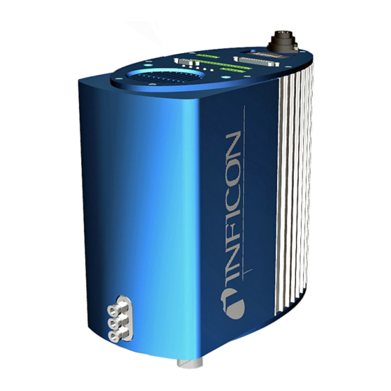
INFICON Description | 4 4.2 Design of device Basic unit The main unit is only called a “device” in the following as long as the meaning remains clear. Fig. 1: Front view “IN” connection, measurement “OUT” connection, pump inlet connection “REF” connection, reference inlet... - Page 14 4 | Description INFICON Interface plate, top view and base plate Fig. 2: Top view and base plate Power supply unit connection RS-232 connection PROFIBUS connection I•Stick connection Control unit connection Thermal circuit breaker (CONTROL UNIT) (resettable) PLC interface (PLC IN/OUT)
- Page 15 INFICON Description | 4 Interface description 1. Power supply unit connection The positive pole is marked with “1+” and the negative pole with “2+”. The other 2 pins have no function. For more information see Electrical data [} 21]. 2. PROFIBUS connection (optional) This device can be controlled using a PROFIBUS.
- Page 16 4 | Description INFICON Measurement and Along with the device, you receive 2 identical lines with a length of 0.5 m with a filter. reference line One line is used to connect the measurement chamber to the device, the other sucks in reference air, see Settings for the measurements [} 51].
-
Page 17: Accessories (Not Included In The Shipment)
Description | 4 4.3 Accessories (not included in the shipment) Control unit connection cable Use this cable to connect the control unit to the T-Guard2. Connector mated set The connector mated set contains Phoenix connectors, with which you can modify the following cables: •... -
Page 18: Control Unit
4 | Description INFICON 4.3.1 Control unit You can operate the device via an external control unit. There are two versions of the control unit – one for table-top operation and another for rack installation. Fig. 4: Control Unit for Desktop Operation Fig. 5: Control unit for rack installation... -
Page 19: Connector Mated Set
INFICON Description | 4 4.3.3 Connector mated set The connector mated set contains Phoenix connectors, with which you can modify the following cables: • PLC • Analog recorder 4.3.4 Fore pump Fig. 6: Fore pump (example) The fore pump sucks the air from the measurement chamber and guides it to the T- Guard2. -
Page 20: Technical Specifications
4 | Description INFICON 4.4 Technical specifications 4.4.1 Mechanical data Dimensions (B × H × T) 130 mm × 271 mm × 272 mm Weight 6.8 kg Line connections 6 mm quick connectors Screw thread IN / REF line 1/8˝ M-NPT Noise level < 56 dB (A) 4.4.2 Ambient conditions... -
Page 21: Electrical Data
INFICON Description | 4 4.4.3 Electrical data Supply voltage 24 V DC ± 16 % / max. 6 A Power consumption, typical 70 Watt Protection class IP 40 Overvoltage category Thermal circuit breaker (resettable) 7 A, inert 4.4.4 Physical data Max. -
Page 22: Factory Settings
4 | Description INFICON 4.4.5 Factory settings Setting Value Control unit Language English Trigger level 1 2 x 10 mbar l/s Trigger level 2 1 x 10 mbar l/s Leak rate of the test leak 1 x 10 mbar l/s... -
Page 23: Installation
INFICON Installation | 5 5 Installation 5.1 Setup WARNING Danger from moisture and electricity Moisture entering the device can lead to personal injury due to electric shocks as well as damage to property due to short circuiting. ► Only operate the device in dry environments and only in buildings. - Page 24 5 | Installation INFICON 8,3 mm max. 10 mm Fig. 8: Functionality of the circuit breaker Rubber feet (4x) Thermal circuit breaker (resettable) Ventilation grill with filter During installation, make sure that: The device is sufficiently ventilated at the top and bottom of the device.
-
Page 25: Operating Modes And Measurement Setup
► Arrange pumps with oil seal below the unit or lay the line so that no oil can get to the unit. The T-Guard2 can be used to measure in 3 different operating modes: • Accumulation measurement • Carrier gas measurement •... -
Page 26: Measurement Setup For Accumulation Measurement
5.2.1 Measurement setup for accumulation measurement Select the most helium-free environment possible for the measurement setup. For reliable measurements with the T-Guard2, the helium content in the air must be less than 10 ppm. By nature, air contains 5 ppm (0.0005%) helium. - Page 27 • Fore pump All vacuum pumps can be used with a gas flow of more than 200 sccm at a basic pressure of under 50 mbar. INFICON offers a suitable pump as an accessory. • Reference line To protect the sensor, helium may not enter the reference line. Therefore, only outside air or fresh air may be sucked into the reference line.
-
Page 28: Carrier Gas Measurement Setup
5.2.2 Carrier gas measurement setup Select the most helium-free environment possible for the measurement setup. For reliable measurements with the T-Guard2, the helium content in the air must be less than 10 ppm. By nature, air contains 5 ppm (0.0005%) helium. - Page 29 • Fore pump All vacuum pumps with a gas flow of more than 200 sccm at a basic pressure of under 50 mbar can be used as a fore pump. INFICON offers a suitable pump as an accessory. T-Guard2_Operating-instructions-jina85en1-13-(2009)
-
Page 30: Connecting An External Control Unit
5 | Installation INFICON 5.3 Connecting an external control unit NOTICE Material damage due to connection error. If you insert or remove the plug during operation, the device could be damaged. ► Only insert or remove the cable when the device is disconnected from the power supply. -
Page 31: Connecting To The Power Supply System
INFICON Installation | 5 5.4 Connecting to the power supply system NOTICE Material damage if power supply pack has the wrong specifications or is connected improperly A power supply pack that has the wrong specifications or is connected improperly can destroy the unit. -
Page 32: Connecting The Plc Inputs To The Electrical System
5 | Installation INFICON 5.5 Connecting the PLC inputs to the electrical system WARNING Danger due to components subjected to electrical overload Material damage or personal injury can result from current that is too high at the inputs and outputs. - Page 33 INFICON Installation | 5 Pin 7 is the common negative pole for all inputs and is connected to the negative pole of the voltage source. The allocation of functions for pins 1 to 6 can be changed, 5.6 Connecting the PLC inputs to the electrical...
- Page 34 5 | Installation INFICON Factory setting Function TRIGGER 1 ERROR/WARNING READY MEASURE STANDBY REC. STROBE WARNING CAL ACTIVE COMMON Pin 16 is the common pole for all outputs. The pin can be used either as a positive or negative pole.
-
Page 35: Connecting The Analogue Outputs To The Electrical System
INFICON Installation | 5 5.7 Connecting the analogue outputs to the electrical system Technical data for the analogue outputs Fig. 15: Pin numbering for the analogue outputs Analog output 1 PIN 1 0…10 V PIN 2 Mass Analog output 2 PIN 3... -
Page 36: Connecting Measurement, Reference And Vacuum Lines
5 | Installation INFICON 5.9 Connecting measurement, reference and vacuum lines Use the filters supplied. They protect the lines from blockages and the sensor from dust. Measurement and reference lines cannot be shortened. If the length of the line or its inner diameter is changed, the measurement speed and the measurement results are affected. -
Page 37: Operation
30 minutes. If the warm-up phase has not yet completed after 30 minutes, the device is released with a warning message. INFICON recommends continued operation of the device with a running fore pump even if not in use. -
Page 38: Recurring Function Symbols
6 | Operation INFICON 6.3.1 Recurring function symbols The keys are always assigned with the following functions and labeled with the shown symbols. Calls the main menu. Calls a window again that was closed with Calls up information Software version, operating hours, serial number, date and time, warning and malfunction messages. -
Page 39: Measurement Display Elements
INFICON Operation | 6 6.3.2 Measurement display elements The measured leak rates are shown numerically. The other elements of the measurement view are shown in the following Figure. Fig. 17: Measurement display elements Selected set of parameters 6 Trigger value Flashing bell: trigger value 1... -
Page 40: Basic Settings
6 | Operation INFICON 6.4 Basic settings Before making your first measurement, set the device using the following menu. • Settings > Miscellaneous • Display • Settings > Interfaces • User authorization You can access the menus via the main menu First, set the language. -
Page 41: Selecting A Pressure Unit
INFICON Operation | 6 6.4.2 Selecting a pressure unit Continuous measurement only: To be able to interpret the measurement result, you need the pressure that is displayed with it. You can choose between the following pressure units: • atm • Torr •... -
Page 42: Calibrate
6 | Operation INFICON 6.4.4 Calibrate NOTICE Incorrect calibration because of unsuitable calibration leak An unsuitable calibration leak leads to an incorrect calibration and therefore to incorrect measurement results. ► An accurate calibration is achieved with client-specific calibration leaks by INFICON. -
Page 43: Accumulation Measurement
INFICON Operation | 6 6.4.4.1 Accumulation measurement For the calibration of an accumulation measurement, you must enter the accumulation volume, i.e. the volume of the measurement chamber minus the volume of the calibration leak. If you do not know the accumulation volume, you can carry out a volume test - see below. -
Page 44: Carrier Gas Measurement
6 | Operation INFICON 6.4.4.2 Carrier gas measurement The carrier gas flow can be determined using the carrier gas pump technical data, or by installing a mass flow controller. Alternatively, you can carry out a flow test - see below. -
Page 45: Check The Calibration
INFICON Operation | 6 6.4.4.3 Check the calibration When checking the calibration, only the calibration factor is checked and is not written again. The leak rate of the test leak used for the test may differ from the leak rate of the calibration leak. -
Page 46: Setting Up User Authorization
6 | Operation INFICON 6.4.6 Setting up user authorization Access to calibration You can prevent access to calibration: ► Select “Main menu > Access control > Access to CAL function”. Protecting settings You can protect access to the settings with a PIN. -
Page 47: Operation Modes
INFICON Operation | 6 6.5 Operation modes You can carry out measurements in 3 operating modes: • Accumulation measurement • Carrier gas measurement • Continuous measurement (accumulation or carrier gas) 6.5.1 Accumulation measurement If a leaking test object that has been filled with helium under pressure is placed in a closed measurement chamber, the helium concentration in this measurement chamber increases over time. - Page 48 6 | Operation INFICON Helium concentration Accumulation time Start Second GROSS measurement Helium in environment Second FINE measurement Time Waiting time before purge First GROSS measurement Purge time First FINE measurement Measuring time GROSS measurement During the measurement, the switch between GROSS and FINE measurement takes and FINE place automatically.
-
Page 49: Carrier Gas Measurement
INFICON Operation | 6 If the test object passes the second GROSS measurement, the device switches to FINE measurement again. From the difference between the 2 FINE measurement results, the device calculates the leak rate. Turbo measurement If a trigger value greater than 1 × 10 mbar l/s per liter of the net volume is set, the device automatically carries out a turbo measurement. - Page 50 6 | Operation INFICON Leak rate display of a carrier gas measurement Fig. 21: Leak rate display of a carrier gas measurement with information on the helium background of the sensor and the surroundings The time required to achieve a constant signal in carrier gas mode (final value) depends on the gas flow and the volume in the measurement chamber.
-
Page 51: Continuous Measurement
INFICON Operation | 6 6.5.3 Continuous measurement For the continuous measurement, expert knowledge from the helium leak test department is required. During the continuous measurement, the device provides continuous measurement results, but as sensor current in amperes rather than as a leak rate. It is therefore not possible to set a trigger value. - Page 52 6 | Operation INFICON ► In the main menu, select “Trigger > Trigger level 1” or “… Trigger level 2”. Setting range: • Trigger level 1 1.0 × 10 to 15 mbar l/s. • Trigger level 2 2.5 × 10 to 15 mbar l/s.
- Page 53 INFICON recommends a purge time of > 4 sec. Automatic purging can also be switched off. Then you have to manually begin the purge after each measurement.
- Page 54 This is possible when measuring in a nitrogen-filled chamber. So that the T-Guard2 does not interpret the complete absence of helium as a malfunction, you need to switch off the corresponding monitoring (minimum current test): ► In the main menu, select “Settings > Monitoring > Without He (N2)”.
-
Page 55: Starting The Measurement
INFICON Operation | 6 6.7 Starting the measurement Waiting time before the After closing the measurement chamber, wait for a defined amount of time, which is start (only for carrier calculated as follows: gas measurement) Start The measurement is started with the interface or with the selection of “Start”. During the measurement, bars display the measurement progress. -
Page 56: Helium Contamination
6 | Operation INFICON 6.8 Helium contamination The sensor is well protected from helium contamination. Every measurement cycle begins with a GROSS measurement. The sensitivity of the sensor is limited during the GROSS measurement. The subsequent FINE measurement is stopped immediately when the following measurement value is reached: •... -
Page 57: Switch Off
INFICON Operation | 6 6.10 Switch off To switch the device off, disconnect it from the power supply. NOTICE Material damage due to helium contamination Helium remaining in the sensor shortens the service life of the sensor and increases the warm-up phase. - Page 58 Cal factor You can display all information on the calibration factor by selecting “Cal factor”. Service The service menu is password-protected. Settings may only be made by the INFICON customer service. 58 / 90 T-Guard2_Operating-instructions-jina85en1-13-(2009)
-
Page 59: Controlling The Device Using Interfaces
INFICON Controlling the device using interfaces | 7 7 Controlling the device using interfaces 7.1 Controlling using PLC The basic functions of the device can be controlled by a PLC, and the measurement values can be read. Most PLC functions are activated when the input signal increases. - Page 60 7 | Controlling the device using interfaces INFICON The current state of all inputs and outputs is displayed. The relays can be switched for testing: 1. Select “Test PLC output”. 2. Using the arrow keys, navigate to the output you want to test.
-
Page 61: Allocation Of Functions For Plc Output
Low resistance means that trigger value 2 has been exceeded. READY Low resistance means that the device is ready for the next measurement. For a continuous measurement, the T-Guard2 measures the reference line. CYCLE Low resistance means that the device is currently carrying out a ACTIVE measurement cycle. - Page 62 High resistance means that trigger value 2 has been exceeded. INV READY High resistance means that the device is ready for the next measurement. In continuous measurement mode, the T-Guard2 measures the reference line. INV CYCLE High resistance means that the device is currently carrying out a ACTIVE measurement cycle .
- Page 63 INFICON Controlling the device using interfaces | 7 INV MEASURE High resistance means that the device is currently measuring. The leak rate of the last measurement is measured if both this output and the REC STROBE output are high resistance.
-
Page 64: Acumulation Measurement Using Plc
7 | Controlling the device using interfaces INFICON 7.1.3 Acumulation measurement using PLC ► Start the measurement when READY is low resistance. The MEASURE output is low resistance during the measurement. After the measurement, the MEASURE output becomes high resistance. If only the REC STROBE output is high resistance again, you can read out the analogue outputs. -
Page 65: Carrier Gas Measurement Using Plc
INFICON Controlling the device using interfaces | 7 7.1.4 Carrier gas measurement using PLC ü The MEASURE output is low resistance during the measurement. ► Start the measurement when READY is low resistance. After the measurement, the MEASURE output becomes high resistance. If only the REC STROBE output is high resistance again, you can read out the analogue outputs. -
Page 66: Controlling Using Rs-232
7 | Controlling the device using interfaces INFICON 7.2 Controlling using RS-232 Almost all of the device’s functions can be controlled with a PC using the RS-232 interface. RTS and CTS are supported. Set the protocol used on the device. -
Page 67: Configuring Analog Outputs
INFICON Controlling the device using interfaces | 7 7.3 Configuring analog outputs The device has 2 separate configurable analog recorder outputs, see Connecting the analogue outputs to the electrical system [} 35]. The outputs have 16-bit resolution and deliver a result after every measurement. In the continuous measurement setting, the renewal rate is 2 Hz. - Page 68 7 | Controlling the device using interfaces INFICON LR Linear The output voltage is linear and proportional to the measured leak rate. The increase is set with the “Analog scale” setting (see below). LR log. The output voltage displays the leak rate logarithmically.
- Page 69 INFICON Controlling the device using interfaces | 7 • In the “LR log” setting, the leak rate is calculated by: (U - 10) / volt / decade) leak rate = final value × 10 For example: A voltage of 3.7 V provides a leak rate of 7.08 × 10 mbar l/s for a final value of 10 mbar l/s and 2 V per decade.
-
Page 70: Save Parameters
8 | Save parameters INFICON 8 Save parameters You can save and call up 4 measurement settings as parameter set in the device. If you use the I•Stick, this number increases to 25. The I•Stick is removable storage developed for the device. You can also use it to easily transfer data to another device. - Page 71 INFICON Save parameters | 8 Inserting the I•Stick On start-up, the device checks whether an I•Stick is inserted. ► With the device switched off, insert the I•Stick into the I•Stick slot. The I•Stick is initialized on first use. Switch the device off and back on again in order to use the I•Stick.
-
Page 72: A.q. - Frequently Asked Questions
– Measurements are less reproducible if you do not use INFICON measurement hoses. Hoses with an inner diameter greater than 1 mm may not be used, since the air in the hose cannot be replaced quickly enough. - Page 73 30 minutes. – You are using a calibration leak that takes time to stabilize. Remedy: Use an INFICON leak. – In your test object, the mixing of helium and air takes too long. Remedy: Evacuate your test object to the greatest extent possible before filling it with helium.
-
Page 74: Warning And Error Messages
10 | Warning and error messages INFICON 10 Warning and error messages During operation, the display shows information that helps you operate the instrument. Measurement values are displayed along with current device modes, operating instructions as well as warnings and error messages. - Page 75 Problem in the sensor Contact INFICON customer faulty electronics service. WISE current not The device was not Let T-Guard2 run for 2 hours. stable used for several days; the sensor current should stabilize after a long run time. Lower the helium background The helium background in the room.
- Page 76 Wise Technology the inlet openings connected sensor to outside air. No helium in the If the problem persists, surroundings (e.g. inlet contact the INFICON openings purged with customer service. nitrogen) Temperature at the Ambient temperature Cool the surroundings, place...
- Page 77 May occur if a software Restart the device.If the EEPROM update to an older problem still exists, contact parameter queue! version is carried out the INFICON customer service. All EEPROM New EEPROM was All settings in the software parameters lost! installed, EEPROM on...
- Page 78 10 | Warning and error messages INFICON If the message occurs Contact INFICON customer constantly during start- service. up, the EEPROM on the system board is defective. EEPROM A parameter was Check the setting of the parameters lost! changed and reset to...
- Page 79 INFICON Warning and error messages | 10 Calibration factor If the calibration factor Check the chamber volume too high! was set to more than 5, settings and/or gas flow the calibration was not successful. If a calibration factor between 2 and 5 was...
-
Page 80: Maintenance
11 | Maintenance INFICON 11 Maintenance 11.1 Replacing the inlet filter There is a filter in both the measurement and reference lines. Check the filter for dirt every 6 months and replace it if necessary. Replace filter at the latest after 2 years. -
Page 81: Replacing Filter Mat On Bottom Of Device
INFICON Maintenance | 11 11.2 Replacing filter mat on bottom of device Filter set Order number 200010027 Required tools Crosshead screwdriver In production rooms with increased dust load, the filter mat on the bottom of the unit can become contaminated. - Page 82 11 | Maintenance INFICON Filter mat change Panhead screw M4x8 mm Filter Grid Filter attachment Filter mats (2x) ü You have a new filter mat. Make sure that the device is disconnected from the power supply by disconnecting the power supply plug.
-
Page 83: Decommissioning
The device consists of materials that can be recycled. This option should be exercised to prevent waste and also to protect the environment. During disposal, observe the environmental and safety regulations of your country. T-Guard2 must not be disposed of in household waste. T-Guard2_Operating-instructions-jina85en1-13-(2009) 83 / 90... -
Page 84: Declaration Of Contamination
13 | Declaration of Contamination INFICON 13 Declaration of Contamination 84 / 90 T-Guard2_Operating-instructions-jina85en1-13-(2009) -
Page 85: Declaration Of Conformity
INFICON Declaration of Conformity | 14 14 Declaration of Conformity T-Guard2_Operating-instructions-jina85en1-13-(2009) 85 / 90... -
Page 86: China Rohs
15 | China RoHS INFICON 15 China RoHS 86 / 90 T-Guard2_Operating-instructions-jina85en1-13-(2009) -
Page 87: Accessories
INFICON Accessories | 16 16 Accessories Accessory part Order no. Control unit for table-top operation 551-100 Operator panel for 19” rack 551-101 Connecting cable for control unit, 5 m 551-102 Connecting cable for control unit, 1 m 551-103 Connector mated set 551-110 I•STICK... -
Page 88: Index
Index INFICON Index Calibration 42 Calibration leak 42 Configuring analog outputs 67 Controlling using PLC 59 Dynamic measurement 50 Error messages 74 GROSS measurement and FINE measurement 48, 50 I•STICK 70 Operation modes 47 Setting the display 41 Standby 56 Waiting and purge time 53...
Need help?
Do you have a question about the T-Guard2 and is the answer not in the manual?
Questions and answers