
Related Manuals for East Tester ET1300


Summary of Contents for East Tester ET1300
- Page 1 ET1300/1301/1302/1303 Programmable DC Electronic Load User Manual Hangzhou Zhongchuang Electronics Co., Ltd.
- Page 2 Hangzhou Zhongchuang Electronics Co., Ltd. Adress: NO. 3 Kangle Road, Gongshu District, Hangzhou,China Postcode: 310015 Telephone: 0086-571-56861333 Fax: 0086-571-56861355 Website: http://www.east-tester.com...
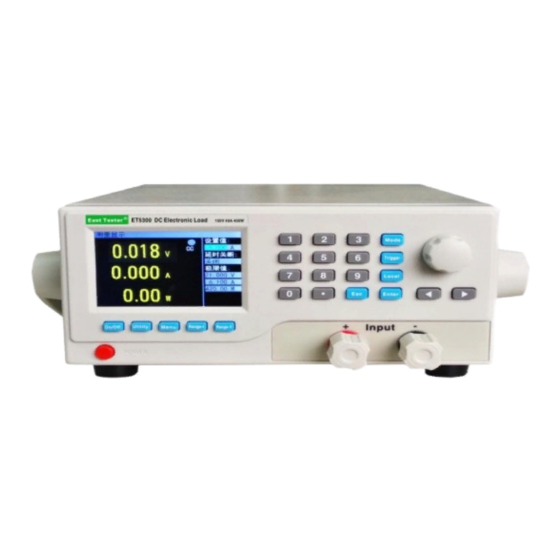
- Page 3 Product Basic Function ET13 series DC programmable electronic load provides 1mV/10mV, 1mA/10mA high resolution and precision with superior performance. It is equipped with 12 common modes and complete test functions, which can be widely used in charger, switching power supply, linear power supply, battery and other production line testing.
-
Page 4: Table Of Contents
Content 1. Quick Start Guide...................... 1 1.1 Front panel LCD display..................1 1.2 Front panel key......................1 1.3 Key Description....................... 2 1.4 Numeric parameter settings..................2 2.Function operation....................3 2.1 Remote/local switching....................3 2.2 System Setup......................3 2.3 Load Setup....................... 4 2.4 Basic mode....................... 4 2.4.1 Constant current mode.................. -
Page 5: Quick Start Guide
ET1301/1302/1303/1304 Programmable DC Electronic Load User Manual Quick Start Guide Front panel LCD display Icon bar: there are five types of icons on the electronic load interface It indicates keyboard lockout It indicates remote control It indicates fan failure Unreg It indicates not satisfy the set value Sense... -
Page 6: Key Description
ET1301/1302/1303/1304 Programmable DC Electronic Load User Manual 1.3 Key Description Key name Function of the key Channel switch key, which is used to control the load channel status: 【On/Off】 on/off. Set the load mode. 【Mode】 For system general settings. 【Utility】 Parameter settings for non-basic mode. -
Page 7: 2.Function Operation
ET1301/1302/1303/1304 Programmable DC Electronic Load User Manual When entering the value in step②: ④press 【Esc】to delete the previous number until all the numbers are deleted. ⑤When all the numbers are deleted, press 【Esc】again to exit the edit mode and end the parameter setting. -
Page 8: Load Setup
ET1301/1302/1303/1304 Programmable DC Electronic Load User Manual 2.3 Load Setup Load setup interface can be entered through the system menu, as shown in figure 2.3.The load range, limit value, off-delay and other related settings can be completed in this interface. Operating instructions: 1. -
Page 9: Constant Voltage Mode
ET1301/1302/1303/1304 Programmable DC Electronic Load User Manual Figure 2.4.1 Constant current mode 2.4.2 Constant voltage mode In constant voltage mode, the electronic load will consume enough current to keep the input voltage at the set voltage. Operating instructions: 1 Select the action item by turning the knob. 2. For parameter settings, please refer to 1.4 Numeric Parameter Setting for details. -
Page 10: Constant Power Mode
ET1301/1302/1303/1304 Programmable DC Electronic Load User Manual 2.4.4 Constant power mode In constant power mode, the load consumes a constant power. When the input voltage changes, the load will adjust the current accordingly to keep the consumed power at the set power value. Operating instructions: 1 Select the action item by turning the knob. -
Page 11: Tran Test
ET1301/1302/1303/1304 Programmable DC Electronic Load User Manual Operating instructions: 1 Select the action item by turning the knob. 2. For parameter settings, please refer to 1.4 Numeric Parameter Setting for details. 3. Press the corresponding【On/Off】 to turn on the load.. Figure 2.4.5 Constant resistance to constant voltage mode 2.5 Tran Test Tran test can be switched back and forth between two currents or voltages set by the load. -
Page 12: List Test
ET1301/1302/1303/1304 Programmable DC Electronic Load User Manual Before starting the Tran test, relevant parameters of Tran test should be set, including: Tran state, level A, level A pulse width, level B, level B pulse width and Tran test mode. The setting interface and the testing interface are shown in figure 2.5.1 and figure 2.5.2 respectively. - Page 13 ET1301/1302/1303/1304 Programmable DC Electronic Load User Manual test outcome interface will appear, as shown in figure 2.6.3. Press【Esc】to return to the main interface of list test. Please refer to the operating instructions for list test outcome interface for details. Operating instructions for list menu: Turn the knob to select the corresponding option, and press 【Enter】to enter the corresponding sub-menu.
- Page 14 ET1301/1302/1303/1304 Programmable DC Electronic Load User Manual Operating instructions for list test outcome interface:1. Press the direction keys 【 】、【 】to switch to” previous page”, “save” or “next page” options. 2. Press the direction key to select the “previous page” or “next page”, and then press[ Enter] to turn the page. 3. Press the direction key to select “save” and press [Enter] to enter the list outcome saving interface, as shown in figure 2.6.5.
-
Page 15: Scan Test
ET1301/1302/1303/1304 Programmable DC Electronic Load User Manual Figure 2.6.5 File list results saving interface Operating instructions for file rename interface: 1. Press the direction key to switch to the edit state before any file can be edited. Switch to “save” and press [Enter] to save the file. If it is a null character, an error will be reported. -
Page 16: Battery Test
ET1301/1302/1303/1304 Programmable DC Electronic Load User Manual Figure 2.7.1 Scan test setting interface Figure 2.7.2 Scan test interface 2.8 Battery Test Battery test is commonly used to test the discharge performance of the battery. The electronic load can work with constant current or constant resistance, which makes it easy to measure the discharge capacity of the battery. -
Page 17: Led Test
ET1301/1302/1303/1304 Programmable DC Electronic Load User Manual 2.9 LED Test The LED equivalent circuit is the series connection of the LED equivalent resistance Rd and the forward voltage Vf. Users need to set three parameters, among which Io is the output current of LED source;... -
Page 18: Short Circuit Test
ET1301/1302/1303/1304 Programmable DC Electronic Load User Manual 2.10 Short Circuit Test The load can simulate a short circuit at the input end. Under the short circuit test, the actual current consumed by the load short circuit depends on the maximum output of the power supply. Operating instructions: 1.Select the action item by rotating the knob;... -
Page 19: Other System Settings
ET1301/1302/1303/1304 Programmable DC Electronic Load User Manual Operating instructions for parameter setting interface: 1.Select the action item by rotating the knob; 2. Press 【 Enter】 to switch set options for non-numeric parameters. 3. As for the setting of numeric parameters, please refer to 1.4 Numeric Parameter Setting for details. -
Page 20: Expansion Port
ET1301/1302/1303/1304 Programmable DC Electronic Load User Manual COM port Interface Pin efinitions DB9 female RS232 USB-Device USB-B female 2.16.2 Expansion port Measure the positive input terminal at the far end Measure the negative input terminal at the far end The list test is in progress, low effectiveness Expansion port output The list test result is qualified, low effectiveness The list test result is unqualified, low effectiveness... -
Page 21: Technical Specifications
ET1301/1302/1303/1304 Programmable DC Electronic Load User Manual Technical specifications Model ET1300 ET1301 Power 400W Rated input Input voltage 0-150V Input current 0-40A 0-60A Range 0.1~19.999V,0.1~150.00V CV mode Resolution 1mV,10mV Accuracy ±(0.05%+0.02%FS) Range 0~3.000A,0~40.00A 0~6.00A,0~60.00A CC mode Resolution 1mA,10mA Accuracy ±(0.05%+0.05%FS) Range 0.05Ω~1 kΩ,1 kΩ~4.5kΩ... - Page 22 ET1301/1302/1303/1304 Programmable DC Electronic Load User Manual Model ET1302 ET1303 Power 400W Rated input Input voltage 0-500V Input current 0-15A 0-30A Range 0.1~19.999V,0.1~500.00V CV mode Resolution 1mV,10mV Accuracy ±(0.05%+0.02%FS) Range 0~3.000A,0~15.00A 0~3.000A,0~30.00A CC mode Resolution 1mA,10mA Accuracy ±(0.05%+0.05%FS) Range 0.05Ω~1 kΩ,1 kΩ~4.5kΩ CR mode Resolution 10mΩ,100mΩ...
Need help?
Do you have a question about the ET1300 and is the answer not in the manual?
Questions and answers