Sign In
Upload
Download
Table of Contents
Contents
Add to my manuals
Delete from my manuals
Share
URL of this page:
HTML Link:
Bookmark this page
Add
Manual will be automatically added to "My Manuals"
Print this page
×
Bookmark added
×
Added to my manuals
Manuals
Brands
East Tester Manuals
Test Equipment
ET5410
User manual
East Tester ET5410 User Manual
Single channel dc electronic load
Hide thumbs
1
2
3
4
Table Of Contents
5
6
7
8
9
10
11
12
13
14
15
16
17
18
19
20
21
22
23
24
25
page
of
25
Go
/
25
Contents
Table of Contents
Bookmarks
Table of Contents
Table of Contents
One、Quick Get Start
Front Panel LCD Display
Front Panel Key
Key Description
Two、Functional Operation
Remote / Local Handover Operation
System Setup Operation
Load Setup Operation
Basic Mode Operation
Constant Current Measurement Mode
Constant Voltage Measurement Mode
Constant Resistance Measurement Mode
Constant Power Measurement Mode
Constant Current Transfer Voltage Measurement Mode
Constant Voltage Transfer Voltage Measurement Mode
Dynamic Test Operation
List Test Operation
Scan Test Operation
Battery Test Operation
LED Test Operation
Short Circuit Test Operation
Protection Function
Trigger Function
Qualification Test Operation
Other System Settings
Keyboard Lock Function
External Interface Function
Four、Technical Specifications
Advertisement
Quick Links
1
One、Quick Get Start
2
Constant Current Measurement Mode
3
Dynamic Test Operation
4
Battery Test Operation
5
External Interface Function
6
Four、Technical Specifications
Download this manual
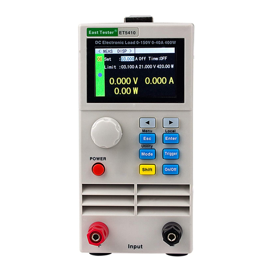
ET5410、ET5411 Single channel DC
electronic load
User's Manual
Hangzhou ZHONG CHUANG Electronics Co., Ltd.
Safety precautions
I
Table of
Contents
Previous
Page
Next
Page
1
2
3
4
5
Advertisement
Table of Contents
Need help?
Do you have a question about the ET5410 and is the answer not in the manual?
Ask a question
Questions and answers
Related Manuals for East Tester ET5410
Test Equipment East Tester ET5411 User Manual
Single channel dc electronic load (25 pages)
Test Equipment East Tester ET5420 User Manual
Double channel programmable dc power load (23 pages)
Test Equipment East Tester ET5300 User Manual
Programmable dc electronic load (22 pages)
Test Equipment East Tester ET5301 User Manual
Programmable dc electronic load (22 pages)
Test Equipment East Tester ET51 Series User Manual
Dc low resistance tester (24 pages)
Test Equipment East Tester ET510 User Manual
Dc low resistance tester (24 pages)
Test Equipment East Tester ET5420A+ User Manual
Programmable double-channel dc electronic load (25 pages)
Test Equipment East Tester ET547X User Manual
Portable electronicload (10 pages)
Test Equipment East Tester ET1300 User Manual
Programmable dc electronic load (22 pages)
Test Equipment East Tester ET-2715 User Manual
Current and voltage calibrator (26 pages)
Test Equipment East Tester ET-AY30 User Manual
Pressure calibrator (21 pages)
Test Equipment East Tester ET2725A User Manual
Multifunction process calibrator (38 pages)
Test Equipment East Tester ET44 Series Manual
Benchtop digital bridge (24 pages)
Test Equipment East Tester ET4401 Manual
Benchtop digital bridge (24 pages)
Test Equipment East Tester ET4410 Manual
Benchtop digital bridge (24 pages)
Test Equipment East Tester ET3325 User Manual
Function/ arbitrary waveform generator (61 pages)
This manual is also suitable for:
Et5411
Table of Contents
Save PDF
Print
Rename the bookmark
Delete bookmark?
Delete from my manuals?
Login
Sign In
OR
Sign in with Facebook
Sign in with Google
Upload manual
Upload from disk
Upload from URL


Need help?
Do you have a question about the ET5410 and is the answer not in the manual?
Questions and answers