
Related Manuals for East Tester ET5420


Summary of Contents for East Tester ET5420
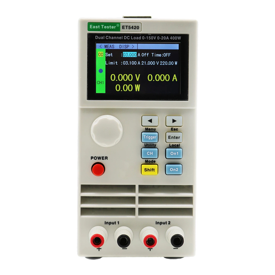
- Page 1 ET5420 double channel Programmable DC power load User manual Hangzhou Zhongchuang Electron Co.,Ltd...
- Page 2 Basic Information ET54 series single/double channel programmable dc electronic load, USES the hi gh performance chip, high speed, high precision design, provide 1mV、 1mA resolution, superior performance, can be widely applied to the charger, switching power supply, linear power supply, production test of all kinds of batteries and other industries, sci entific research institutions such asthe test research and development.
- Page 3 General technical specifications: Power voltage: 220Vac±10%, optional 110Vac±10%, 45-65hz Display: 2.8-inch TFT LCD, resolution 320 x 240 Operating temperature: 0 ℃ to 40 ℃ Storage temperature: - 10 ℃ to 70 ℃ Relative humidity: < 80% Interface: standard USB Device, RS232(or 485) Size: 90mm * 190mm * 300mm (width * height * depth) Standard accessories: One three-core power cord...
-
Page 4: Table Of Contents
Catalog 一、Quick Reference.......................... 1 1.1 Front Panel Display ....................... 1 1.2Front Panel Press........................1 1.3Press Introduction ........................1 二、Function Operation ........................2 2.1 Remote/ Local Switch Opertion ....................2 2.2 System Setting Operation......................2 2.3 Load Setting operation ......................3 2.4 Basic Mode operation ......................3 2.4.1Constant Current Test Mode ..................... -
Page 5: 一、Quick Reference
一、Quick Reference 1.1 Front Panel 1.2Front Panel Press 1.3 Key Manual General function key Shortcut function key CH1/CH2 switching Shift+Menu Non-basic mode parameter settings On1、On2 CH1/CH2 switch Shift+Esc return Trigger Trigger key Shift+Mode Mode selection Enter Enter Shift+Utility System common settings Cursor left and right Shift+Local Remote local switching... -
Page 6: 二、Function Operation
二、Function Operation Before testing the pending test source by load, In order to ensure the stable and safe operation of the load, please be sure that after connecting the load and pending testing source by the way of red positive and black negative, turn on power output firstly , then turn on the load. -
Page 7: Load Setting Operation
2.3 Load Setting Operation Through the system menu, you can enter the load setting interface, as shown in Figure 2.3. In this interface, the relevant settings for the load range, limit value, delay off, etc. can be completed. Operation instructions: 1. Select the operation item by turning the knob. 2. Non-numeric parameters Press [Enter] to switch the setting options. -
Page 8: 2Constant Voltage Test Mode
In constant current mode, the electronic load consumes a constant current regardless of whether the input voltage changes. Operation instructions: 1. Press the [CH] key to select the operation channel; 2. Select the operation item by rotating the knob; 3. Set the parameters. Press [Enter] to enter the edit mode, use the arrow keys to select the corresponding number of digits, then adjust the value by turning the knob, [Enter] or [Shift] + [▶] (Esc) to exit editing;... -
Page 9: Constant Resistance Test Mode
2.4.3 Constant Resistance Measurement Mode In constant resistance mode, the load is equivalent to a constant resistance, and the load will consume a correspondingly varying current as the input voltage changes. Operation instructions: 1. Press the [CH] key to select the operation channel; 2. Select the operation item by rotating the knob;... -
Page 10: Constant Current Switch To Voltage Test Mode
2.4.5 Constant Current Switch to Constant Voltage Measurement Mode The constant current voltage measurement mode is to prevent damage to the source under test due to overcurrent discharge. In this mode, when the source to be tested cannot output the current value set by the load, it will automatically switch from the constant current mode to the constant voltage mode. -
Page 11: Dynamic Mode Test Operation
Fig 2.4.5 Constant Resistance Switch to Constant Voltage Measurement Mode 2.5 Dynamic Test Operation The dynamic test operation can be repeatedly switched between two load setting currents or voltages. This function can be used to test the dynamic characteristics of the power supply. Before starting the dynamic test operation, the dynamic test related parameters need to be set. - Page 12 Pulse mode: In this mode, after the test is started, the load will switch from the A value to the B value every time a trigger signal is received, and then switch to the A value after maintaining the B value pulse width time.
-
Page 13: Listing Mode Test Operation
Fig 2.5.2 Dynamic Test Interface 2.6 List Testing Mode The list test function can conveniently test the working condition of the source to be tested under different load conditions, which is beneficial to the automatic test of the production line. By pre-setting the steps of the list test, the test steps and test parameters of the source to be tested can be edited into a list and a series of tests can be completed in order. - Page 14 Test interface operation instructions: Press the corresponding [On1], [On2] to start or close the mode. Fig 2.6.1 List Set Interface Fig 2.6.2 List Test Interface Fig 2.6.3 List Result Interface List test result save interface operation instructions: 1. Select the file by rotating the knob; 2. Use the arrow keys to switch to the edit state to edit the file.
-
Page 15: Scanning Mode Test Operation
Fig 2.6.4 File List Setting Parameter Storage Interface Fig 2.6.5 File List Result Storage Interface File naming interface operation instructions: 1. Use the arrow keys to switch to the editing state to edit the file file, switch to save and press [Enter] to save the file, if it is a null character, report an error; 2. Edit the character by rotating the knob Press [Enter] to type the character;... -
Page 16: Battery Test Operation
Parameter setting interface operation instructions: 1. Press [Shift] + [◀] (Menu) in the main interface of the scan test to enter the scan setting interface; 2. Select the operation item by rotating the knob; 3. Press the [Enter] key for non-numeric parameters. Switch the setting options;... -
Page 17: Led Test Operation
keys to select the corresponding number of digits, then rotate the knob to adjust the value, [Enter], [Shift] + [▶] (Esc) Exit editing; 5. Press [Shift] + [▶] (Esc) to return to the previous interface. Test interface operation instructions: Press the corresponding [On1], [On2] to start or close the mode. - Page 18 voltage exceeds the turn-on voltage of the diode, the load starts to work, and the LED drive power can be truly reflected. With load capacity. Operation instructions: 1. Press the [CH] key to select the operation channel; 2. Select the operation item rotating the knob;...
-
Page 19: Short Circuit Test Operation
2.10 Short Circuit Test Operation The load can simulate a short circuit at the input. In the short-circuit test, the actual current value consumed by the load short-circuit depends on the maximum output of the power supply. Operation instructions: 1. Press the [CH] key to select the operation channel; 2. Select the operation item by rotating the knob;... -
Page 20: Qualified Test Operation
key on the front panel). 2. External (trigger by triggering the port on the rear panel). 3. Bus (triggered by program control instructions of the RS-232 or 485 bus interface). 2.13 Qualified Test Operation The qualification test is an additional function of the basic measurement mode CC/CV/CR/CP. -
Page 21: Outer Interface Function
The load also adds locking Function to prevent users' error.The title bar displays the lock id.In locked state except [On/Off], [Enter], [Shift] + [▶] button, the rest of the buttons including knobs are locked.In addition, in the lock state, the icon bar will appear lock icon, icon disappear when unlocked.Long press [Enter] key with 3s can switch between lock and unlock state. - Page 22 10mS. Fig 2.15.2 Communication Set Interface Technical Specification Model ET5420 Power 400W (Double channel 200W*2) Rated Input Input Voltage 0-150V Input Current 0-40A(20A per channel) Measurement 0.1~19.999V,0.1~150.00V...
- Page 23 Read back Resolution Rate 1mV,10mV Accuracy ±(0.05%+0.1%FS) Range 0~3.000A,0~20.00A Current Resolution Rate 1mA,10mA Read back Accuracy ±(0.05%+0.1%FS) Range 200W Power Resolution Rate 10mW Read back Accuracy ±(0.1%+0.5%FS) Scope of Protection Over Voltage Protection >155V over voltage protection Over Current Protection >...
Need help?
Do you have a question about the ET5420 and is the answer not in the manual?
Questions and answers