
Related Manuals for East Tester ET3325


Summary of Contents for East Tester ET3325
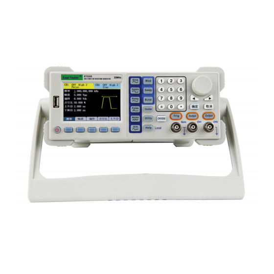
- Page 1 ET3325 Function/ Arbitrary Waveform Generator User Manual HANGZHOU ZHONGCHUANG ELECTRON CO., LTD...
-
Page 2: Table Of Contents
Contents Introduction to ET3325 Function/ Arbitrary Waveform Generator..........3 Key Features............................3 Product Model............................. 3 1. Quick Start............................4 1.1 Introduction to Front and Rear Panels.................. 4 1.2 Introduction to Interface......................4 1.3 Waveform Setup........................5 1.4 Output Setup..........................7 1.5 Modulation/Frequency Sweep/Burst Output Setup.............. 7 1.6 Introduction to Digital Input.................... - Page 3 3.1 Product Technical Indicators....................53 3.2 General Technical Specifications..................59 4. Appendices..........................59 Appendix A: Accessories......................59 Appendix B: Maintenance and Cleaning.................. 60...
-
Page 4: Introduction To Et3325 Function/ Arbitrary Waveform Generator
File management supporting USB flash disk and local storage ET3325 output with the highest output frequency is ET3310 Model is 10MHz, ET3325 Model is 25MHz,ET3340 Model is 40MHz, ET3360 Model is 60MHz and ET 3370 Model is 70MHz. -
Page 5: Quick Start
1. Quick Start 1.1 Introduction to Front and Rear Panels This section describes front and rear panels of for your quick understanding of function and usage. Front panel includes liquid crystal, keys and output terminal and so on. Keys include: Function/mode, reusable keys, numeric keys and direction keys/knobs. -
Page 6: Waveform Setup
Basic operation interface is shown in Figure 1-3. Figure 1-3 Interface 1.3 Waveform Setup There is a series of keys with waveform displaying on the right of the operation panel, which are sine wave, square wave, ramp wave, pulse wave, noise wave and arbitrary wave. There is a common key as well: switch of CH1/CH2 channels. - Page 7 4. Press , waveform display area will turn to pulse signal and show Pulse in the status area. Pulse waves of different parameter values are accessible through the setup of frequency/cycle, amplitude/high-level, offset/low-level, symmetry and rising/trailing edge. 5. Press , waveform display area will turn to noise signal and show Noise in the status area.
-
Page 8: Output Setup
1.4 Output Setup As shown in Figure 1-5, there are ET3325 Output keys at the bottom right of the front panel for channel output control andET3310 Trig key for trigger output. The following examples will offer you guidance on these functions. -
Page 9: Introduction To Digital Input
1.6 Introduction to Digital Input As shown in Figure 1-7, ET3325 sets of keys are on the front panel, which are numeric keypad, left-right direction keys and knobs and confirmation/cancellation key. The following specifications will offer you guidance on the use of digital input. -
Page 10: Introduction To Functions Of Frequency Meter/System Setup/Help
1.7 Introduction to Functions of Frequency Meter/System Setup/Help As shown in Figure 1-8, ET3340 keys are below keys of modulation/frequency sweep/burst on the front panel to set frequency meter, system setup and help respectively. The following specifications will offer you guidance on the setup of these functions. Figure 1-8 Keys of Frequency Meter/System Setup/Help 1. -
Page 11: Basic Waveform Setup
2.1 Basic Waveform Setup 2.1.1 Sine wave setup Press and operation menu of sine wave will be displayed at the bottom of the screen. Channel basic information is displayed on the upper left, including channel switch, output impedance and name of current waveform. Set output waveform of sine wave through its operation menu. - Page 12 1. Press →frequency to set frequency parameter value. The displayed frequency is either the power-on default value or the frequency previously selected., Use the current value if the frequency value is valid for the new waveform when changing parameters. To set waveform cycle, press the softkey of Frequency once again and switch to the Cycle softkey (current option is in inverse display).
- Page 13 Figure 2-3 Setup Parameter Value of Amplitude Note: The maximum amplitude will turn to 5Vpp if frequency is higher than 20MHz under 50Ωoutput. Set offset voltage 1. Press →offset to set parameter value of offset voltage. The displayed offset voltage is either the power-on default value or the offset previously selected. Use the current value if the offset is valid for the new waveform when changing parameters.
-
Page 14: Square Wave Setup
Set initial phase 1. Press →phase to set parameter value of initial phase. The displayed initial phase is either the power-on default value or the phase previously selected. Use the current value if the phase is valid for the new waveform when changing parameters. 2. - Page 15 Figure 2-6 Display Interface of Setup of Square Wave Parameters Table 2-2 Square Waveform Menu Description Functional Menu Setup Description Frequency/cycle Set waveform frequency or —— cycle Amplitude/high-level Set waveform amplitude or —— high-level Offset/low-level waveform offset —— low-level Duty cycle Set duty cycle of square wave ——...
-
Page 16: Set Ramp Wave
Figure 2-7 Setup Parameter Value of Duty Cycle 2.1.3 Set ramp wave Press and the operation menu of ramp wave will be displayed at the bottom of the screen. Use operation menu of ramp wave to set its output waveform parameters. Major parameters of ramp wave include frequency/cycle, amplitude/high level, offset/low level, symmetry and phase. - Page 17 Figure 2-8 Display Interface of Setup of Parameter Values of Ramp Waveform Table 2-3 Ramp Waveform Menu Description Functional menu Setup Description Frequency/cycle Set waveform frequency or —— cycle Amplitude/high-level Set waveform amplitude or —— high-level Offset/low-level waveform offset —— low-level Symmetry Set symmetry of ramp wave...
-
Page 18: Set Pulse Wave
Figure 2-9 Setup parameter value of symmetry 2.1.4 Set pulse wave Press and the operation menu of pulse wave will be displayed at the bottom of the screen. Use operation menu of pulse wave to set its output waveform parameters. Major parameters of pulse wave include frequency/cycle, amplitude/high-level, offset/low-level, pulse width/duty cycle and rising edge/falling edge. - Page 19 Table 2-4 Pulse waveform menu description Functional menu Setup Description Frequency/cycle Set waveform frequency or —— cycle Amplitude/high-level Set waveform amplitude or —— high level Offset/low-level waveform offset —— low-level Duty cycle/pulse width Set duty cycle or pulse width —— of pulse wave Rising edge/falling edge Set rising and falling edge of...
-
Page 20: Set Noise Wave
Note: 1. Pulse width is restricted by minimum pulse width and pulse period Minimum pulse width: 20ns; Pulse width ≥ minimum pulse width; Pulse width ≤ pulse period-minimum pulse width 2. Pulse duty cycle is restricted to minimum pulse width and pulse period Pulse duty cycle ≥... -
Page 21: Set Arbitrary Wave
Figure 2-12 Display Interface for Setup of Parameter Values of Noise Waveform Table 2-5 Noise Waveform menu Description Functional menu Setup Description Amplitude/high-level Set waveform amplitude or —— high-level Offset/low-level waveform offset —— low-level 2.1.6 Set arbitrary wave Press and the operation menu of arbitrary wave will be displayed at the bottom of the screen. - Page 22 Load, create and edit the user arbitrary wave Arbitrary wave loading Thirty ET3325 arbitrary waves are built in the signal generator which also provides 10 nonvolatile storage locations and arbitrary waveform the storage user defined. To select ET3310 of the arbitrary waves, press →...
- Page 23 1. Press → Waveforms →Loading →Built-in and enter the following interface. 2. Position the desired waveform by the knobs or direction keys. 3. Select the waveform.
- Page 24 Figure 2-15 Built-in Arbitrary Waves Table 2-8 Built-in Waveforms of Arbitrary Waveform Functional Setup Description menu NegRamp/AttALT/AmpALT/StairUP/ Common Select common waveforms Halfsin/StairUD/StairDn/PPluse ExpRise/ExpFall/Tan/Cot/ Select common mathematical Mathematics Sqrt/Arb_X2/Sinc/Gauss functions Window Boxcar/Barlett/Triang/Blackman/ Select common window functions functions Hamming/Hanning/Kaiser DC/Composite/Tanh/Coth/Gamma/ Others Select other waveforms Legendre/chebyshev/Bessel/StepResp Selection ——...
- Page 25 Choose stored arbitrary waveforms 1. Press → Waveforms →Loading → Storage and enter the following interface. 2. Choose the way of local or U disk. 3. Position the desired waveform by the knobs or direction keys. 4. Read waveform data. Figure 2-16 Read Stored Waveforms Table 2-9 Stored Arbitrary Waveform Menu Description Functional menu...
- Page 26 Table 2-17 User Arbitrary Waveform Creation Interface Table 2-10 Arbitrary Waveform Creation Menu Description Functional menu Setup Description Points —— Set the points of waveforms needing edit. Upper limit —— Set a creating point voltage upper limit. Lower limit —— Set a creating point voltage lower limit.
- Page 27 Figure 2-18 Point Edit Interface Store waveforms After waveforms created, press Store to enter the storage function interface, as shown in Figure 2-19, and store the waveform in nonvolatile memory or external memory. Figure 2-19 Store Edited Arbitrary Waveforms Note: In the nonvolatile storage, only ET3310 waveform can be stored in each waveform storage location, and the old wave will be overwritten when a new ET3310 stored in.
- Page 28 Figure 2-20 Arbitrary Wave Edit Interface Table 2-11 Arbitrary Wave Edit Menu Description Functional menu Setup Description Select arbitrary waveforms need to be edited, which can be built-in Select —— arbitrary waveforms, arbitrary waveforms or volatile waveforms stored in the volatile storage. Upper limit ——...
-
Page 29: Modulation Waveform Setup
2.2 Modulation Waveform Setup Press to output modulated waveforms. function signal generators can output modulation waveforms of AM, FM, PM, ASK, FSK and PSK. Set different modulation parameters according to different modulation types. In amplitude modulation, internal modulation/external modulation, frequency, depth and modulation waveforms can be set. - Page 30 Figure 2-21 AM Waveform Parameter Setup Interface Table 2-12 AM Parameter Setup Menu Description Functional menu Setup Description Types Select AM Signal source Internal/external Select internal modulation/external modulation Frequency Set modulation wave frequency (2mHz~20kHz) Depth Set amplitude variation depth (0%~120%) Internal modulation Select internal modulation signal...
-
Page 31: Frequency Modulation (Fm)
Signals Description Sine wave Sine Square wave of 50% duty cycle Square Ramp (Triangle) of 50% symmetry Triangle Up Ramp UpRamp Down Ramp DownRamp 2.2.2 Frequency Modulation (FM) Modulated waveforms consist of carrier waves and modulation waveforms. In FM (Frequency Modulation), the frequency of the carrier wave changes with the instantaneous voltage of the modulation waveform. -
Page 32: Phase Modulation (Pm)
Frequency Set modulation wave frequency (2mHz~20kHz) Frequency Set the offset between the frequency of modulation Internal offset and the carrier. modulation Select internal modulation signal: Modulation wave Sine/Square/Triangle/UpRamp/DnRamp When external modulation is selected, the External Frequency modulation signal is input by the [Modulation modulation offset In] on the rear panel. - Page 33 Figure 2-23 PM Waveform Parameter Setup Interface Table 2-14 PM Parameter Setup Menu Description Functional menu Setup Description Types Select PM Signal source Internal/external Select internal/external modulation Frequency Set modulation wave frequency (2mHz~20kHz) Set the offset between the phase of modulation and Internal Phase offset the carrier.
-
Page 34: Amplitude Shift Keying (Ask)
Amplitude and Modulation Amplitude ). The amplitude at which the output shifts between carrier amplitude and modulation amplitude is called ASK amplitude. The frequency at which the output shifts between these ET3325 amplitudes is determined by the internal frequency generator or the signal level on the rear-panel [Ext Trig] connector. -
Page 35: Frequency Shift Keying (Fsk)
Modulation amplitude(High Z) can vary from 0V to 10V, the default value is 2V. 2.2.5 Frequency Shift Keying (FSK) FSK modulation is to shift its output frequency between ET3325 preset values (Carrier Frequency and the Hop Frequency). The frequency at which the output shifts between carrier frequency and hop frequency is called FSK frequency. -
Page 36: Phase Shift Keying (Psk)
Only Hop Frequency parameters need to be set. 2.2.6 Phase Shift Keying (PSK) PSK modulation is to shift its output phase between ET3325 preset values (Carrier Phase and the Modulation Phase). The phase at which the output shifts between carrier phase and modulation phase is called PSK phase. - Page 37 between carrier phase and modulation phase is determined by the specified PSK frequency. When the external modulation is selected, PSK frequency cannot be adjusted and is determined by the signal level on the rear-panel [Ext Trig] connector. When a logic high level is present, the carrier phase is output.
-
Page 38: Frequency Sweep Waveform Setup
The modulating signal of internal modulation is a 50% Modulation phase duty cycle square wave. Set modulation phase range When the external modulation is selected, the modulation signal is input by the [Ext Trig] on the rear External Modulation phase modulation panel. - Page 39 Select Trigger Source Internal: select internal trigger source External: select external trigger source with [Ext Trig] connector on rear-panel Signal source Internal/external/manual Manual: select manual trigger, and each time you press Trig, a sweep will start, and a continuous press of the key will trigger the signal generator once again.
-
Page 40: Burst Waveform Setup
2.4 Burst Waveform Setup Burst key can provide users with burst output of various waveform function, and it can output waveforms of specific number (N-cycle burst) continuously; when applying to external gate signal (gated burst), any wave function (except noise and DC) can be used. Press to set the output waveform parameters in burst mode by operating the burst operation menu. - Page 41 Cycle number Set the output cycle number of each N-cycle burst string (1 - 65535). If necessary, the burst period will increase to adapt the specified number of cycles. Phase Define the start and stop points of the burst. The phase can be set from 0 to 360°, with default of 0°.
- Page 42 Table 2-20 Infinite Burst Parameter Setup Menu Description Functional Setup Description menu Types N-cycle/infinite/gated Select burst output type: infinite Select Trigger Source: External: select external trigger source, use [Ext Trig] Signal External/manual connector on rear-panel source operating Manual: select manual trigger, and each time you press Trig, a burst will output, and a continuous press of the key will trigger the signal generator once again.
-
Page 43: Sync Output (Ch1)
2.5 Sync Output (CH1) Sync output provides CH1 channel sync output, and all standard functions (except DC and noise) have a related sync signal. When sine wave and triangle wave are outputted, the sync signal is square wave with 50% duty cycle. -
Page 44: Frequency Meter
2.6 Frequency Meter Frequency meter adopts single-channel frequency measurement, with measurable signal range of 1Hz - 160MHz. Press to enter the interface shown below, and the frequency values measured is shown in the central screen. The external signal is input by the [Counter] interface on the rear panel. Figure 2-31 Frequency Meter Interface Note: When there is an external frequency signal input, the screen value will refresh regularly;... -
Page 45: Assist System Function Setup
2.7 Assist System Function Setup Press to set the channel output parameters, system configuration information, file storage, check interface information, perform machine calibration and system upgrades, and inspect system information. Figure 2-32 Assist System Function Setup Interface Channel output parameters include load/impedance setup of Channel 1 and Channel 2 ... -
Page 46: System Setup
1. Press →CH1→Select to enter Channel 1 output impedance setup interface and set the load value of the Output connector, with specific interface being shown below. Figure 2-33 Channel 1 Output Parameter Setup To set the output impedance as 50Ω, press 50Ω; to set high impedance, press High Z. 2. -
Page 47: File Storage
Table 2-22 System Setup Menu Functional Setup Description menu Buzzer —— Set switch of buzzer Language —— Set the display language Light 0-100 Set the screen brightness Select Language ET3340 is equipped with a user interface in both Chinese and English for users to choose. To select the language displayed by the OS, →... - Page 48 Table 2-23 File Storage Menu Functional menu Setup Description Types State/Arb Files Set the file types needed to be operated State File: Instrument state files Arb File: Arbitrary wave files Contents — Enter Contents interface — Back — Back to the previous interface —...
- Page 49 Arb Data Files Storage Users can store the Arb data file at any ONE/10MHZ of the 10 non-volatile storage locations. There already exists data file at the currently selected location, and then the new data file will overwrite the old ONE/10MHZs. Specific operations for Arb data files storage are as follows: 1.
- Page 50 the file in the U-disk. 3. Eject the U-disk In the file storage interface, if there is currently insert U-disk, there will be Ejection option and press the Ejection key to eject the U-disk. After the U-disk ejected, the pattern disappears. Figure 2-38 USB Storage Usage File name Input The file name input supports only English characters, and in U-disk storage, the input characters...
-
Page 51: Interface
2. When editing an wrong file name, use the left and right keys to move the cursor to select the wrong letters you want to delete, press the Delete soft key to delete and re-edit the file name to be input; 3. -
Page 52: System Information
contact local dealer if you need upgrade file package. 2.7.7 System information System information includes the serial number of the machine and version number of the software and hardware. 2.8 Help function signal generator has a built-in help system to provide related help for some common operations, and users can use a list of help topics to get operational guidelines about some of the keys on the front panel. -
Page 53: Telecommunication
7) Output preserved arbitrary waveform 5. How to get help Check how to get help. 6. Technical support For technical support, please contact the local dealer. 2.9 Telecommunication ET3340 supports standard USB or RS232 interface to communication with the computer to realize arbitrary waveform downloading. -
Page 54: Technical Specifications
3. Technical Specifications Unless specified otherwise, all technical specifications apply to ET3325 function/arbitrary waveform generators. Signal generator must meet the following requirements at first to meet these specification standards: The instrument must work continuously in a specified operating temperature (18 ℃ - ... - Page 55 Frequency Characteristics ET3310 ET3325 ET3340 ET3360 ET3370 Waveform Sine, square, triangle, pulse, noise and arbitrary waves (including DC) types Sine 1uHz~10MHz 1uHz~25MHz 1uHz~40MHz 1uHz~60MHz 1uHz~70MHz Square 1uHz ~ 5MHz 1uHz ~ 5MHz 1uHz~10MHz 1uHz~10MHz 1uHz~10MHz 1uHz~500kHz 1uHz~500kHz 1uHz~1MHz 1uHz~2MHz 1uHz~2MHz...
- Page 56 Ramp Wave Characteristics Linearity ≤0.1% Peak output degree 0.0~100.0%(resolution 0.1%) Symmetry Pulse Wave Characteristics Pulse Min20ns; 1ns resolution width Edge Min 20ns; transition time Overshoot <5% Jitter 6ns+0.1% Period Arbitrary Wave Characteristics Sampling 160MSa/S speed Waveform amplitude 12bits resolution Waveform amplitude 10bits resolution...
- Page 57 ±0.1dB,≤100kHz Flatness ±0.3dB,≤5MHz (relative to ±0.4dB,≤45MHz 1K Sine, ±1dB,≤70MHz 1 Vpp) ±0.1dB,≤100kHz Flatness ±0.2dB,≤5MHz (relative to ±2dB,≤40MHz 1K Sine, 1 ±5dB,≤70MHz Vpp) Offset (50Ω) ±5Vpk , ac + dc Range ±1.5Vpk , ac + dc Range ±(1% set value+5mV+0.5% amplitude) Accuracy Output 50Ω...
- Page 58 Modulation Sine, square, triangle and ramp wave Modulation 2mHz~20kHz frequency Frequency 0~Maximum carrier frequency offset FSK Modulation (CH1) Carrier Sine, square, ramp, pulse and arbitrary waveforms (excluding DC) wave Source Internal/external Modulation Square wave of 50% duty ratio wave Keying 2mHz~1MHz frequency ASK Modulation (CH1)
- Page 59 Types Linearity/Logarithm Start/Stop 1uHz~Maximum carrier frequency Frequency Sweep 1ms~500s frequency time Trigger Manual operating, internal, external source Burst characteristics (CH1) Carrier Sine, square, ramp, pulse, noise and arbitrary waveforms (excluding DC) wave Pulse 1~65535 or infinite, gated count Start/stop 0~360° phase Internal 1us~500s...
-
Page 60: General Technical Specifications
range 3.2 General Technical Specifications Power Supply Supply voltage 200~240V, 45~65Hz Power < 40W consumption Display Types 3.5-inch TFT LCD screen Resolution 480×320 Color 16M color Environment: Operation: 10℃~+40℃ Temperature Non-operation: -10℃~+60℃ range Cooling Natural cooling methods Below +35℃: ≤90% relative humidity Humidity range +35℃... -
Page 61: Appendix B: Maintenance And Cleaning
Appendix B: Maintenance and Cleaning General maintenance Please do not place the instrument subjected to sunlight exposure for a long time. Cautions: Do not make any corrosive liquid stain on the instrument, so as not to damage the instrument. Cleaning Clean the instrument regularly based on practice.
Need help?
Do you have a question about the ET3325 and is the answer not in the manual?
Questions and answers