Sign In
Upload
Download
Table of Contents
Contents
Add to my manuals
Delete from my manuals
Share
URL of this page:
HTML Link:
Bookmark this page
Add
Manual will be automatically added to "My Manuals"
Print this page
×
Bookmark added
×
Added to my manuals
Manuals
Brands
East Tester Manuals
Test Equipment
ET44 Series
Manual
East Tester ET44 Series Manual
Benchtop digital bridge
Hide thumbs
1
Table Of Contents
2
3
4
5
6
7
8
9
10
11
12
13
14
15
16
17
18
19
20
21
22
23
24
page
of
24
Go
/
24
Contents
Table of Contents
Bookmarks
Table of Contents
Table of Contents
Installation
Description
General Technical Specifications
Quick Reference
Front Panel
Introduction of Keys
Power On/Off Key
Direction Key
Basic Function Keys
Introduction of Rear Panel
User Interface
Interface of Measurement Display
Interface of Measurement Setting
Interface of List Scanning
Interface of System Setting
Basic Function Operation
Startup & Shutdown
Parameter Selection
Frequency Selection
Level Selection
Offset Selection
Range Selection
Output Impedance Selection
Measurement Display Speed Selection
Main Parameter Selection
Secondary Parameter Selection
Equivalent Mode Selection
Comparator Setting
List Scanning Function
Dcr Mode
Electrolytic Capacitor Mode
Relative Function
Data Retention Function
Data Recording Function (Maximum Value, Minimum Value, Average Value)
Correction Function
Backlight Brightness Setting
Power-On Parameter Setting
Buzzer Switch Setting
Basic Performance Indicators
Measurement Parameter
Equivalent Mode
Basic Accuracy
Dcr Measurement Accuracy
Test Signal Frequency
Test Signal Level
Output Impedance
Measurement Display Range
External Interface Instructions
Usb Interface
Rs232 Interface
Scpi Command Reference
Precautions and Warranty
Advertisement
Quick Links
1
Table of Contents
2
Installation
3
General Technical Specifications
4
Scpi Command Reference
Download this manual
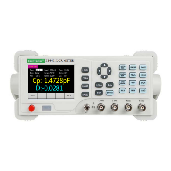
ET44 Series Benchtop digital bridge.
ET4401 LCR METER
Table of
Contents
Previous
Page
Next
Page
1
2
3
4
5
Advertisement
Table of Contents
Need help?
Do you have a question about the ET44 Series and is the answer not in the manual?
Ask a question
Questions and answers
Related Manuals for East Tester ET44 Series
Test Equipment East Tester ET4401 Manual
Benchtop digital bridge (24 pages)
Test Equipment East Tester ET4410 Manual
Benchtop digital bridge (24 pages)
Test Equipment East Tester ET1300 User Manual
Programmable dc electronic load (22 pages)
Test Equipment East Tester ET5410 User Manual
Single channel dc electronic load (25 pages)
Test Equipment East Tester ET5411 User Manual
Single channel dc electronic load (25 pages)
Test Equipment East Tester ET5420 User Manual
Double channel programmable dc power load (23 pages)
Test Equipment East Tester ET-2715 User Manual
Current and voltage calibrator (26 pages)
Test Equipment East Tester ET-AY30 User Manual
Pressure calibrator (21 pages)
Test Equipment East Tester ET2725A User Manual
Multifunction process calibrator (38 pages)
Test Equipment East Tester ET3325 User Manual
Function/ arbitrary waveform generator (61 pages)
Test Equipment East Tester ET5300 User Manual
Programmable dc electronic load (22 pages)
Test Equipment East Tester ET5301 User Manual
Programmable dc electronic load (22 pages)
Test Equipment East Tester ET51 Series User Manual
Dc low resistance tester (24 pages)
Test Equipment East Tester ET510 User Manual
Dc low resistance tester (24 pages)
Test Equipment East Tester ET5420A+ User Manual
Programmable double-channel dc electronic load (25 pages)
Test Equipment East Tester ET547X User Manual
Portable electronicload (10 pages)
This manual is also suitable for:
Et4401
Et4402
Et4410
Table of Contents
Save PDF
Print
Rename the bookmark
Delete bookmark?
Delete from my manuals?
Login
Sign In
OR
Sign in with Facebook
Sign in with Google
Upload manual
Upload from disk
Upload from URL


Need help?
Do you have a question about the ET44 Series and is the answer not in the manual?
Questions and answers