Sandpiper G Series Service & Operating Manual
Heavy duty flap valve
Hide thumbs
Also See for G Series:
- Service & operating manual (22 pages) ,
- Service & operating manual (25 pages)
Table of Contents
Advertisement
Quick Links
SERVICE & OPERATING MANUAL
Original Instructions
Certified Quality
ISO 9001 Certified
ISO 14001 Certified
Certified to CSA Technical Letter No, R-14
Certified to ANSI LC6-2008
Warren Rupp, Inc.
A Unit of IDEX Corporation
800 N. Main St.,
Mansfield, Ohio 44902 USA
Telephone (419) 524.8388
Fax (419) 522.7867
SANDPIPERPUMP.COM
© Copyright 2017 Warren Rupp, Inc.
All rights reserved
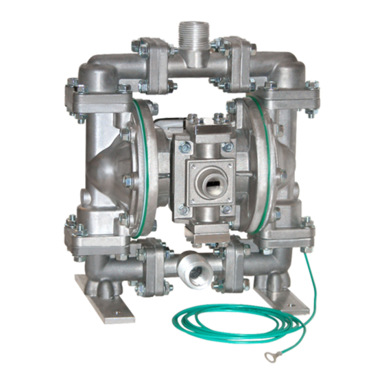
Model G20F
Heavy Duty Flap Valve
Design Level 1
s a n d p i p e r p u m p. c o m
Advertisement
Table of Contents

Related Manuals for Sandpiper G Series


Summary of Contents for Sandpiper G Series
- Page 1 SERVICE & OPERATING MANUAL Original Instructions Certified Quality Model G20F Heavy Duty Flap Valve Design Level 1 ISO 9001 Certified ISO 14001 Certified Certified to CSA Technical Letter No, R-14 Certified to ANSI LC6-2008 Warren Rupp, Inc. A Unit of IDEX Corporation 800 N.
- Page 2 Safety Information IMPORTANT WARNING When used for toxic or aggressive fluids, the pump should Read the safety warnings and instructions in this manual always be flushed clean prior to disassembly. before pump installation and start-up. Failure to comply with the recommendations stated in this manual could damage the pump and void factory warranty.
- Page 3 Temperature Tables Table 1. Category 1 & Category 2 ATEX Rated Pumps Ambient Temperature Process Temperature Temperature Maximum Surface Tem- Range [°C] Range [°C] Class perature [°C] -20°C to +80°C T100°C -20°C to +108°C T135°C -20°C to +60°C -20°C to + 160°C T200°C -20°C to +177°C (225°C) T2 Per CSA standards ANSI LC6-2018 US & Canadian Technical Letter R14, G-Series Natural Gas Models are restricted to (-20°C to + 80°C) process temperature Table 2. Category 2 ATEX Rated Pumps Equipped with Pulse Output Kit or Integral Solenoid: Options Ambient Temperature Process Temperature...
-
Page 4: Table Of Contents
Table of Contents SECTION 1: PUMP SPECIFICATIONS ....1 • Explanation of Nomenclature • Performance • Materials • Dimensional Drawings SECTION 2: INSTALLATION & OPERATION ...4 • Principle of Pump Operation • Recommended Installation Guide • Troubleshooting Guide SECTION 3: EXPLODED VIEW ......7 •... -
Page 5: Explanation Of Nomenclature
Explanation of Pump Nomenclature Your Model #: ____ ____ (fill in from pump nameplate) Pump Pump Check Design Wetted Diaphragm/ Check Valve Non-Wetted Porting Pump Muffler Pump Brand Size Valve Level Material Check Valve Seat Material Options Style Options Options Model #: Pump Brand Non-Wetted Material Options... -
Page 6: Performance
Performance G20F NATURAL GAS OPERATED SUCTION/DISCHARGE PORT SIZE • 2" CAPACITY MODEL G20F Performance Curve • 0 to 208 gallons per minute Performance based on the following: elastomer fitted pump, flooded suction, water at ambient temperature. AIR CONSUMPTION The use of other materials and varying hydraulic conditions may result in deviations in excess of 5%. SCFM (M 3 /hr) (0 to 786 liters per minute) 10(17) -
Page 7: Dimensional Drawings
Dimensional Drawings G20F Metallic Dimensions in inches (metric dimensions in brackets). Dimensional Tolerance .125" (3mm). 13.56 21.64 7.06 OPTIONAL VERTICAL SUCTION PORT 2.59 2"NPT SUCTION PORT 2.61 3/4" NPT AIR INLET 20.30 19.87 17.69 9.81 2.55 2.61 2"NPT OPTIONAL VERTICAL 2.64 DISCHARGE PORT DISCHARGE PORT... -
Page 8: Principle Of Pump Operation
UNIVERSAL ALL AODD Principle of Pump Operation Principle of Pump Operation Air-Operated Double Diaphragm (AODD) pumps are powered by The pump primes as a result of the suction stroke. The suction stroke lowers (P3) compressed air, natural gas or nitrogen. the chamber pressure increasing the chamber volume. -
Page 9: Recommended Installation Guide
Recommended Installation Guide 020.064.000 Filter VENTING WARNING: This filter is equipped with a stainless steel manual drain. The port is 1/8" NPT. When draining moisture from the filter, first shut off the natural gas supply. 020.059.000 REGULATOR WITH GAGE PRESSURE WARNING: This regulator is to be installed at point of use with the pump. The maximum gas supply is 400psi. Full line pressure needs to be regulated below 400psi prior to the regulator installation position. -
Page 10: Troubleshooting Guide
Troubleshooting Guide Symptom: Potential Cause(s): Recommendation(s): Pump Cycles Once Deadhead (system pressure meets or exceeds gas Increase the inlet gas pressure to the pump. Pump is designed for 1:1 pressure ratio at zero flow. supply pressure). (Does not apply to high pressure 2:1 units). Gas valve or intermediate gaskets installed incorrectly. -
Page 11: Composite Repair Parts Drawing
Composite Repair Parts Drawing ITEM TORQUE: 360 IN-LBS (40 N-m) TORQUE: 480 IN-LBS (54 N-m) Service & Repair Kits 476.359.360 Nitrile Gas End Kit Nitrile Seals, Bumpers, O-rings, and Gaskets, Retaining Rings, Plungers, Bushings Gas Valve Assembly with Nitrile O-rings Pilot Valve Assembly with O-rings 476.359.363 FKM Gas End Kit FKM Seals, Bumpers and O-rings, Nitrile Gaskets, Retaining Rings, Plungers, Bushings Gas Valve Assembly with FKM O-rings Pilot Valve Assembly with FKM O-rings 476.360.360 Nitrile Gas End Wear Kit Nitrile Seals, Bumpers, O-rings, and Gaskets, Retaining Rings, Plungers, Bushings 476.360.363... -
Page 12: Composite Repair Parts List
Composite Repair Parts List Item Part Number Description Item Part Number Description 031.208.360 Air Valve Assy (with Nitrile O-rings) 1 545.007.110 Nut, Hex 7/16-14 031.208.363 Air Valve Assy (with FKM O-rings) 1 (stainless wetted only) 070.006.571 Bushing, Intermediate 547.002.110 Nut, Nylon Stop 1/4 x 20 (included in item #4) 560.001.360 O-ring (Buna) -
Page 13: Material Codes
R E C YC L I N G (Some Applications) 644..Santoprene /PTFE ® (Compression Mold) 656 ..Santoprene Diaphragm and ® Many components of SANDPIPER AODD ® 359..Urethane Rubber Check Balls/EPDM Seats pumps are made of recyclable materials. 360..Nitrile Rubber Color coded: RED 661..EPDM/Santoprene ®... - Page 14 Air Distribution Valve Assembly Air Distribution Valve Assembly Air Distribution Valve Servicing See repair parts drawing, remove screws. Step 1: Remove Hex Head Cap Screws (1-G). Step 2: Remove end cap (1-F), gasket (1-E) and bumper (1-C). Step 3: Remove spool part of (1-B) (caution: do not scratch). Step 4: Press sleeve (1-B) from body (1-A).
-
Page 15: Gas Valve Assembly
Pilot Valve Assembly Pilot Valve Assembly Pilot Valve Assembly with Nitrile O-rings Item Part Number Description 095.073.002 Gas Pilot Valve Assembly 095.070.558 Gas Pilot Valve Body Pilot Valve Servicing 755.025.001 Pilot Valve Sleeve Assembly 560.033.360 O-Ring With Pilot Valve removed from pump. 775.026.000 Pilot Valve Spool Assembly Step 1: Remove snap ring (3-F). - Page 16 Step 2: Reassembly: There are two different types of diaphragm plate assemblies utilized throughout the Step 8: On opposite side of pump, thread the Sandpiper product line: Outer plate with a threaded remaining assembly onto the diaphragm rod. Using a stud, diaphragm, and a threaded inner plate.
-
Page 17: Pumping Hazardous Liquids
Pumping Hazardous Liquids When a diaphragm fails, the pumped liquid or fumes enter the natural gas NATURAL GAS EXHAUST ILLUSTRATION end of the pump. Fumes are exhausted into the surrounding environment. When PUMP INSTALLATION AREA pumping hazardous or toxic materials, the exhaust gas must be piped to an SAFE GAS appropriate area for safe disposal. - Page 18 Certifies that Air-Operated Double Diaphragm Pump Series: HDB, HDF, M Non-Metallic, S Non-Metallic, M Metallic, S Metallic, T Series, G Series, U Series, EH and SH High Pressure, RS Series, W Series, F Series, SMA and SPA Submersibles, and Tranquilizer Surge Suppressors comply with ®...
- Page 19 II 2 D Ex h IIIB T100°C...T200°C Db • Metallic pump models with external aluminum components (S Series, HD Series, G Series, DMF Series, MSA Series, U Series, F Series, T Series, EH Series, SH Series, GH Series ) •...
Need help?
Do you have a question about the G Series and is the answer not in the manual?
Questions and answers