Advertisement
Quick Links
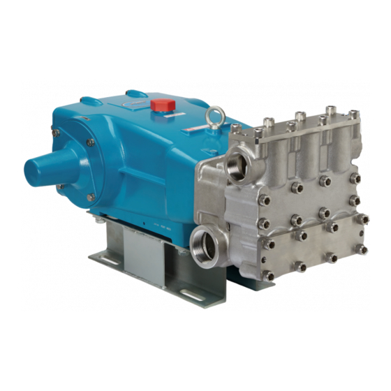
SERVICE MANUAL
67102 PLUNGER PUMP
FLOW
PUMP
MODEL
gpm
lpm
67102
100.0
378.5
67102C
100.0
378.5
IMPORTANT SAFETY INSTRUCTIONS
It is the responsibility of the user to read and understand all instructions, important safeguards, and safety precautions before operating or
servicing any pump. Failure to do so may result in property damage, personal injury or death.
General Safety Information and Symbols
Pay special attention to the following signal words, safety alert symbols and statements:
DANGER
indicates a hazardous situation which, if not avoided, will result in death or serious injury.
WARNING
indicates a hazardous situation which, if not avoided, could result in death or serious injury.
CAUTION
indicates a hazardous situation which, if not avoided, could result in minor or moderate injury or property damage.
NOTICE
indicates a hazardous situation which, if not avoided, could result in property damage.
Indicates a potential personal injury hazard. Obey all safety messages that follow this symbol to avoid possible injury or death.
SERVICING THE 67102 PLUNGER PUMP SERIES
WARNING
Do not service pump or electrical equipment while energized.
Electricity can cause personal injury, death or property damage.
1.
Adhere to "Lock Out" and "Tag Out" procedures for electrical equipment.
2.
Before commencing pump service, turn power supply off.
3.
Keep water away from electrical outlets and electrical devices.
4.
Electrical components must be installed by a qualified
electrician to avoid risk of electrocution.
PRESSURE
RPM
psi
bar
Pump
1,000
69
680
1,000
69
680
TEMPERATURE
Motor
˚F
˚C
—
140
60
—
140
60
SHAFT DIA.
OIL CAPACITY
in
mm
oz
1.772
45
320
1.772
45
320
l
9.46
9.46
Advertisement

Subscribe to Our Youtube Channel
Related Manuals for CAT Pumps 67102


Summary of Contents for CAT Pumps 67102
- Page 1 Indicates a potential personal injury hazard. Obey all safety messages that follow this symbol to avoid possible injury or death. SERVICING THE 67102 PLUNGER PUMP SERIES WARNING Do not service pump or electrical equipment while energized.
-
Page 2: Servicing The Valves
Servicing the Valves DISASSEMBLY NOTE: Two (2) valve kits are required to repair the pump (see data sheet PN 99DAT023). NOTE: Discharge and inlet valve assemblies are identical (use procedure below for disassembly and reassembly of discharge and inlet valves). 1.0 Use a M14 socket wrench to remove the 1.1 Remove valve plate. - Page 3 REASSEMBLY NOTE: Lubricate o-rings on valve seats and valve plugs prior to reassembly. 1.9 Place new preassembled valve assembly 1.10 Install spring washer onto spring retainer 1.12 Install valve plug by hand and then tap into each valve chamber. and then coil spring. with a rubber hammer to seat properly.
- Page 4 Servicing the Seals and Plungers DISASSEMBLY FOR SEALS NOTE: One (1) seal kit is required to repair pump (see data sheet PN 99DAT023). NOTE: In order to replace seals, remove discharge and inlet manifolds. CAUTION Exercise extreme caution when removing discharge manifold.
- Page 5 2.8 Use a pick to remove o-ring from the one 2.9 Remove large coil spring positioned 2.10 Use a M14 socket wrench to remove end of the inlet spacer. around each plunger. the top outside two (2) M16 x 110 HSH screws on the inlet manifold.
- Page 6 DISASSEMBLY FOR SEALS CONTINUED 2.16 Remove male adapter from each 2.17 Remove the pair of white v-packings 2.18 Remove female adapter from each from each seal chamber. seal chamber. seal chamber. 2.19 V-Packing assembly arrangement. 2.20 Turn inlet manifold over so crankcase side is facing upward. 2.21 Use a large flat tip screwdriver to remove low-pressure seal from each seal chamber.
- Page 7 REASSEMBLY FOR SEALS NOTE: Examine inlet and discharge manifolds, spacers, male and female adapters for grooves, pitting or wear and replace as needed. NOTE: Examine o-rings, low-pressure seals and v-packings for cuts or wear and replace with a new seal kit as needed. 2.22 With crankcase side of inlet manifold facing upward, install low-pressure seals with coil spring facing down.
- Page 8 DISASSEMBLY FOR PLUNGERS 2.31 Remove seal retainers. 2.32 Seal retainer assembly 2.33 Use a M30 hex wrench to loosen the plunger retainers. 2.34 Grasp ceramic plunger and turn 2.35 Remove keyhole washer. 2.36 Remove barrier slinger. counterclockwise to remove plunger 2.37 Remove plunger retainer from from plunger rod.
- Page 9 REASSEMBLY OF PLUNGERS NOTE: Lubricate o-rings and backup-rings on plunger retainers prior to reassembly. 2.40 Install gasket onto each plunger retainer. 2.41 Position o-ring into groove of each plunger retainer. 2.42 Position backup-ring into groove on top of o-ring of each plunger retainer. 2.43 Insert plunger retainer assembly into ceramic plunger.
- Page 10 REASSEMBLY OF MANIFOLDS 2.50 Place inlet manifold onto two (2) M16 x 277 studs and slide up against crankcase. 2.51 Install large coil spring over each ceramic plunger and press into place. 2.52 Apply Loctite®242® to six (6) M16 x 110 HSH screws; insert screws into inlet manifold and hand thighten.
-
Page 11: Preventive Maintenance Schedule
It is a good practice to replace both low and high pressure seals and inspect plungers when leaks are present. Cat Pumps recommends using our custom-blend premium grade hydraulic oil formulated to meet Cat Pumps specifications. For best results, perform an initial oil change after the first 50 hours of operation and every 500 hours thereafter. If other oil is used, oil change should be performed every 300 hours of operation. -
Page 12: General Safety Information And Symbols
General Safety Information and Symbols DANGER A. FLAMMABLE OR EXPLOSIVE LIQUID HAZARD Do not operate pump with flammable or explosive liquids unless extraordinary safety precautions are observed. Leaks of flammable or explosive liquids, if exposed to elevated temperatures, static electricity, sparks or other hazards, will result in flame or possible explosion, causing serious personal injury, death or property damage. - Page 13 F. OVER PRESSURIZATION HAZARD Do not operate high pressure pumping system unless extraordinary safety precautions are observed. A high pressure pumping system can deadhead or over pressurize causing serious personal injury and property damage. 1. All high pressure systems require a primary pressure regulating device (i.e., regulator or unloader) and a secondary pressure safety relief device (i.e., pop-off valve, safety valve, rupture disc) to assure proper pressure setting and overpressure protection.
- Page 14 1. Cat Pumps custom-blend oil is available worldwide in 21 oz. bottles, cases, or 5 gallon twin packs. Use of other oils may void the warranty.
-
Page 16: Diagnosis And Maintenance
A careful review of the necessary inlet conditions and protection devices required before the system is installed will eliminate many potential problems. Cat Pumps are very easy pumps to service and require far less frequent service than most pumps.
Need help?
Do you have a question about the 67102 and is the answer not in the manual?
Questions and answers
How do you remove the crankshaft oil seal of the 67dx?
To remove the crankshaft oil seal of the CAT Pumps 67DX, remove the bearing cover and then replace the o-ring and/or oil seal.
This answer is automatically generated