Table of Contents
Advertisement
Quick Links
Advertisement
Table of Contents

Related Manuals for NatComm DP5


Summary of Contents for NatComm DP5
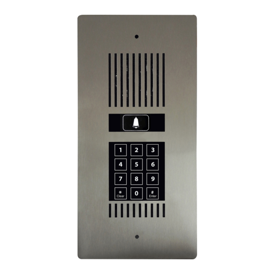
- Page 1 DEALER USER GUIDE For Technical Assistance Please Phone: (07) 5596 5128...
- Page 2 Back Panel Front Face Lock 1 Lock 2 Controller Width = 130 mm Width = 91 mm Height = 264 mm Depth = 31 mm Height = 200 mm DP5 is supplied with a TWO YEAR FACTORY WARRANTY Page 2 Natcomm...
- Page 3 DP5 can operate at distances of up to 300 meters from the Controller, providing high quality cabling such as CAT5 is used. Up to two Door Phones (Models DP1 to DP5) can be connected to the one DOOR STATION CONTROLLER. This allows for a Door Phone to be located at two different locations.
-
Page 4: Rain Protection
DP5’s Touch Switch technology eliminates the possibility of water entering via the trigger switch or keypad. DP5’s speaker is made of a plastic mylar material and great effort has been taken to maximise weather proofing of all electronic components. If DP5 is exposed to direct rain, we strongly recommend that you use our optional... -
Page 5: Mounting The Door Phone
MOUNTING THE DOOR PHONE DP5 should be mounted at the average face height of 5 feet (1.5meter) for optimum performance. The main body of the DP5 unit is designed to be recessed into a wall surface. To speed up Flush Mount installations, a WMB-3 ‘Wall Mount box’... -
Page 6: Door Phone Performance
DOOR PHONE PERFORMANCE DP5 is IDEAL for RESIDENTIAL USE or COMMERCIAL USE, where ROAD NOISE is NOT HIGH. It is not designed for INDUSTRIAL USE where ambient noise can be constantly high. The volume of the audio communication on the internal phones should be... -
Page 7: Operation
Enter a 4, 5 or 6 digit User Access Cod e Press Enter Then Note: the # key is also labelled Enter If an incorrect entry is made Press Clear Note: the * key is also labelled Clear Natcomm Page 7... -
Page 8: Controller Wiring
LOCK 2 WHITE Supplied 8 wire ORANGE LOCK 1 LOCK 1 BROWN connection box for connection of BLACK POWER POWER YELLOW 1 or 2 Lock Release power supplies RED AUDIO AUDIO GREEN CAT5 CABLE or SOLID CORE CABLE Page 8 Natcomm... - Page 9 Two Lock Strikes (used for Pedestrian Lock/Gate access) to the One or Two internal relays of the DS Control Unit. You should also connect one leg of the internal relay of DP5 (or one leg of both relay’s if required) to the same terminals of the connection box. See diagram page 11.
- Page 10 DP5 unit. DOOR PHONE AUDIO & POWER Connection At DP5, the supplied 4 position phoenix plug that plugs into DP5 should be wired as follows : The RED WIRE of the connection box, carries one leg of the Audio Signal. It must connect to EITHER centre position (pin 2 or 3) of the supplied Phoenix plug.
- Page 11 These relays can then be closed by the User by pressing : ** (for lock 1) *2 (for lock 2) On any telephone, which will cause power to connect to the lock for a preset time, allowing the lock or gate to open. Natcomm Page 11...
- Page 12 The supplied connection box (if used) should have one leg of the power supply for One or Two Lock Strikes already connected to it. You can also connect the internal relays of DP5 to the same terminals of the connection box, if convenient (see Figure If you wish to position the connection box close...
- Page 13 The DP5 lock control relays can then be closed at any time by a User or visitor entering a valid ACCESS CODE. This will cause power to connect to the lock for a preset time, which will allow the gates to open.
- Page 14 Page 14 Natcomm...
- Page 15 Natcomm Page 15...
-
Page 16: Programming Options
One Dealer Programming Code is allowed. This Code is used to set up the Owner Code, User Codes and all DP5 Settings. The Default Dealer code is: 888888 The Dealer Code can be changed to any 4, 5 or 6 digit number. - Page 17 Input of the DEALER PROGRAMMING CODE will allow : INCORRECT CODE LOCKOUT TIME If enabled, the default LOCK OUT time for DP5 is 5 minutes. You can change the Lockout Time from 01 to 99 minutes. Allowable Range 01 to 99 minutes...
- Page 18 PROGRAMMING PROCEDURE Owner Code will allow ENTRY or DELETION of User Codes (page 18 only). Dealer Code will allow SET UP of ALL DP5 parameters (pages 18 and 19). Two Beeps after any parameter entry signifies a valid entry. Four Beeps after any parameter entry signifies an invalid entry.
- Page 19 DP5 PROGRAMMING with Dealer Code ONLY C. SET DP5 FOR OPERATION WITH TWO RELAYS Note : Entry Required only if Lock Relay 2 is to be used. Press # 7 Press (default mode) for use with 1 relay only Or Press 1...
-
Page 20: Balance Pot Adjustment
DO NOT USE A TELEPHONE IN CLOSE PROXIMITY TO THE DOOR PHONE, as feedback interference will affect the Balance Pot settings. The Balance POT does not increase volume. Moving it when unnecessary may cause a deterioration in audio quality or a loss of audio in 1 direction. Page 20 Natcomm... - Page 21 If quality is becoming worse, please adjust the POT in the other direction and continue with small adjustments until the best communication quality is achieved. Clockwise adjustments will improve Audio at the DP5 Door Phone. Anti-Clockwise adjustments will improve Audio to the internal Telephones Natcomm...
-
Page 22: Led Brightness
This is done by adjusting a Micro Pot, which is located under a white plastic sealing cap (see diagram above). There are 3 separate Micro Pots and White sealing caps on DP5. You should use the Pot located under the Top-Left white sealing cap. You will need to use a small flat blade or star blade screwdriver to make the adjustment. - Page 23 Lock 1 Lock 2 Controller The LOUDNESS of the NUMERIC KEYPAD BEEP on the front panel of the DP5 can be adjusted to suit. This is done by adjusting a Micro Pot, which is located under a white plastic sealing cap (see diagram above).
-
Page 24: Troubleshooting Audio
TROUBLESHOOTING AUDIO If you are having trouble with AUDIO COMMUNICATION between DP5 and TELEPHONES on your line, please follow the procedure below 1) Adjust the POT located on the back of the Door Phone as described on pages 20 - 21. - Page 25 TURN OFF any SWITCH MODE POWER SUPPLIES located near the DS Control Unit to test for Interference. Cordless Phones in particular can suffer or cause EMF problems. Refer to the User Guide of your DOOR STATION Control Unit for detailed troubleshooting instructions. Natcomm Page 25...
- Page 26 ** or *2 is pressed on the attached telephone. Refer to the User Guide of your DOOR STATION Control Unit for more detailed troubleshooting instructions. IMPORTANT NOTE You must not use the Power Adaptor supplied with your DS Control Unit to power your Door Lock/Strike. Page 26 Natcomm...
- Page 27 Door Phone. Adjustment will be needed on both Door Phone Balance Trim pots. This can be time consuming as each may need to be adjusted several times until audio clarity is achieved at both Door Phones. Natcomm Page 27...
-
Page 28: Warranty
Damage caused to this device or attached equipment, by lightning strikes or over voltage surge is not covered under this warranty. UNIT SEALED AT THE FACTORY OPENING THE UNIT WILL VOID THE WARRANTY Page 28 Natcomm...
Need help?
Do you have a question about the DP5 and is the answer not in the manual?
Questions and answers