Advertisement
Advertisement
Table of Contents

Related Manuals for Clarke CUTS1


Summary of Contents for Clarke CUTS1
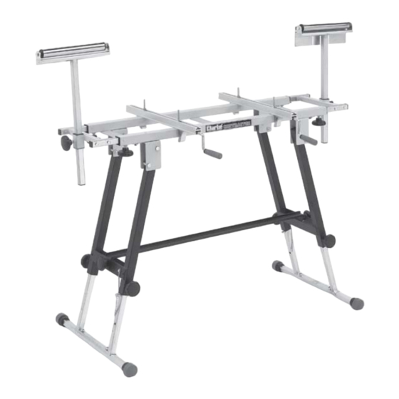
- Page 1 TOOL STAND Model No. CUTS1 ASSEMBLY INSTRUCTIONS 0513...
- Page 2 Storage To store the Tool Stand, the legs need to be collapsed, as follows: Fitrstly remove the Rollers if fitted, and ensure the table extensions are fully IN. Invert the unit and remove the leg brace by unscrewing the two large knobs, securing it.
- Page 3 Clarke dealer, or CLARKE INTERNATIONAL Parts Department, on 020 8988 7400 Guarantee This CLARKE product is guaranteed against faulty manufacture for a period of 12 months from the date of purchase. Please keep your receipt which will be required as proof of purchase.
- Page 4 Assembly Remove the components from the packaging and carefully lay them out, checking to ensure that no damage was suffered during transit. Should any damage be apparent, please contact your Clarke dealer immediately. A. 1 x Frame c/w Legs 4 x M6 x45 Carriage bolt w/nut...
- Page 5 Assembly cont. Place the frame on the floor in the inverted position, i.e. legs uppermost, and raise the legs, so that the brace may be fitted, using two large lock knobs - one at each end, as shown in Fig. 2. Attach the stabilisers, one to each leg, as shown in Figs 3 and 4.
- Page 6 NOTE: Should the tool not have suitable holes for mounting to the table, then the tool should firstly be mounted on to a suitable board of at least 15mm thickness, and the board, with tool, secured to the table, again using the carriage bolt provided.
- Page 7 Notes...
Need help?
Do you have a question about the CUTS1 and is the answer not in the manual?
Questions and answers