Advertisement
Advertisement
Table of Contents

Related Manuals for TDK-Lambda SWS-L Series


Summary of Contents for TDK-Lambda SWS-L Series
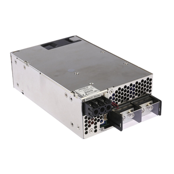
- Page 1 SWS-L Series Compact and high-power AC/DC power supply...
- Page 2 ・All specifications are subject to change without notice.
- Page 3 Low Profile Low Fan Noise The SWS-L series is designed to have a lower The SWS-L is one of the quietest power supplies profile than previous models. With the thin of in their class. A temperature controlled fan 61mm, a 50% size reduction, these can be adjusts its speed automatically, based on the mounted in 2U or smaller locations.
- Page 4 600L SWS600L Specifications ITEMS/UNITS MODEL SWS600L-3 SWS600L-5 SWS600L-12 SWS600L-15 SWS600L-24 SWS600L-36 SWS600L-48 SWS600L-60 Voltage Range (*3) AC85-265 or DC120-350 Frequency (*3) 47-63 Power Factor (115/230VAC) (typ) (*2) 0.98/0.95 % Input Effi ciency (115/230VAC) (typ) (*2) 70/72 75/77 79 / 82 81/84 82 / 84 Current (115/230VAC) (typ) (*2)
- Page 5 600L SWS600L Outline Drawing 3-M4 4-M4 (45) 20MAX 61±1 INPUT TERMINAL (AT THE BOTTOM CHASSIS) NAME PLATE NAME PLATE DC ON INDICATOR L OUTPUT VOLTAGE N ADJUSTMENT FG ー TERMINAL COVER 150±0.5 18.6 4-M5 OUTUT TERMINAL 25MAX 190±1 6MAX 8-M4 NAME PLATE (SCALE : 1 : 1) (ON BOTH SIDES) 150±0.5...
- Page 6 1000L SWS1000L Specifications ITEMS/UNITS MODEL SWS1000L-3 SWS1000L-5 SWS1000L-12 SWS1000L-15 SWS1000L-24 SWS1000L-36 SWS1000L-48 SWS1000L-60 Voltage Range (*3) AC85-265 or DC120-350 Frequency (*3) 47-63 Power Factor (115/230VAC) (typ) (*2) 0.98 / 0.95 Input Effi ciency (115/230VAC) (typ) (*2) × 75 / 77 79 / 81 82 / 84 84 / 86...
- Page 7 1000L SWS1000L Outline Drawing SEE NOTE C ( 16.7 ) 4-M4 AIR FLOW 22 ( MAX) NAME PLATE NAME PLATE (BOTTOM SIDE) OUTPUT TERMINAL (-) OUTPUT TERMINAL (+) ( 14.7 ) 165±0.5 12 13 37 ( MAX ) 3 ( MAX ) 240±1 ( 50.7 ) == NAME PLATE ==...
- Page 8 600L, 1000L Block Diagram PRIMARY SECONDARY MAIN TRANSFORMER CURRENT INRUSH RECTIFIER SENSING LINE CURRENT SMOOTHING SWITCHING INPUT OUTPUT RECTIFIER FILTER CIRCUIT LIMIT FILTER CIRCUIT SMOOTHING 85〜265VAC CIRCUIT FILTER CIRCUIT SENSING CNT2 CONTROL REMOTE CONTROL CIRCUIT CIRCUIT CIRCUIT CONTROL VOLTAGE ADJUST CURRENT SHARING CIRCUIT...
- Page 9 600L, 1000L SWS-L Instruction Manual BEFORE USING THE POWER SUPPLY UNIT Be sure to read the following precautions thoroughly before using ● This power supply is capable of providing hazardous energy this power supply unit. output (240VA), the end equipment manuafacturer must provide Pay attention to all warnings and cautions before using the unit.
-
Page 10: Configuration And Function
600L, 1000L 2. Terminal Explanation Please pay extra attention to the wiring. Incorrect connection C N1, C N 2 , C N 3 C o n n e c t o r p i n will damage the power supply. Configuration and Function Front Panel Explanation CN1 and CN2 are same pin confi... - Page 11 600L, 1000L 3. Terminal Connection Method Please pay extra attention to the wiring. Incorrect connec- SWS1000L tion will damage the power supply. CN1(or CN2) ● When connecting input, output wiring and CN1, CN2, CN3, input AC-Line should be off . twist or shield ● Input wiring and output wiring shall be separated to im- prove noise sensibility. ● The protective earth (PE) must be connected to the ter- minal or chassis. ● Remote sensing lines shall be twisted or used shielded wires. ● Remote ON/OFF control lines shall be twisted or used shielded wires. Separate from load line. ● Output current of each terminal screw shall be 60A or less for SWS600L.
- Page 12 600L, 1000L 4. Functions and Precautions Input Voltage Range Input voltage range is single phase 85 - 265VAC (47 - 63Hz) or Vmax=50V Imax=10mA 120 - 350VDC. Input voltage, which is out of specifi cation, may cause unit damage. Rated input voltage for safety standard application is 100AC-240VAC (50/60Hz).
-
Page 13: Series Operation
600L, 1000L Series Operation For series operation, both method (A) and (B) are possible. 2.2KΩ CNT1 There might be a step in the output rise waveform during series operation. 150Ω CNT2 Method (A) Power Supply Load Example V1:5V R1:620Ω) 2.2KΩ CNT1 Method (B) 150Ω... -
Page 14: Withstand Voltage
600L, 1000L change about 400mV (3V, 5V), 5% (12V, 15V, 24V, 36V, 48V, Output - CNT・AUX・ALM : 100VDC 50MΩ or more 60V) in its transient response. AC(L) Method (A) Isolation AC(N) Tester Power Supply Load CNT1 PC COM CNT2 PC COM Withstand Voltage Method (B) SWS600L is designed to withstand 3.0kVAC, SWS1000L is de-... -
Page 15: Auxiliary Supply
600L, 1000L Output - CNT· AUX · ALM : 100VAC 1min. (100mA) Note 2. For 3.3V output model, limit output voltage variation range at 30% - 120%. At PV voltage variation 1.5V - 6V. For 15V output model, limit output voltage variation range AC(L) at 20% - 130%. -
Page 16: Mounting Directions
600L, 1000L 5. Mounting Directions Mounting Directions Recommended standard mounting method is (A). Method (B) and (C) are also possible. Refer to the derating below. Mounting A, B, C SWS600L (A) Mounting A (B) Mounting B (C) Mounting C Load (%) Ta (... -
Page 17: Wiring Method
600L, 1000L 6. Wiring Method (1) The output load line and input line shall be separated to improve noise sensitivity. (2) The sensing lines shall be twisted and separated from the output lines for remote sensing. Fig.1 (3) Use all lines as thick and short as possible to make lower impedance, clamping core at both input and output wires benefi... - Page 18 600L, 1000L 7. External Fuse Rating Refer to the following fuse rating when selecting the external fuses that are to be used on input line. Surge current fl ows when line turns on. Use slow-blow or time-lag type fuse, not fast-blow fuse.
- Page 19 600L, 1000L 10. Before concluding that the unit is at fault Before concluding that the unit is at fault, make the following If FAN stops, the ALM signal turn “High” level and OTP checks. might be activated. (1) Check if the rated input voltage is connected. (8) Power supply has ventilating holes on the front and back (2) Check if the wiring of input and output is correct.
- Page 20 This datasheet has been downloaded from: www.EEworld.com.cn Free Download Daily Updated Database 100% Free Datasheet Search Site 100% Free IC Replacement Search Site Convenient Electronic Dictionary Fast Search System www.EEworld.com.cn All Datasheets Cannot Be Modified Without Permission Copyright © Each Manufacturing Company...
Need help?
Do you have a question about the SWS-L Series and is the answer not in the manual?
Questions and answers