Table of Contents
Advertisement
Quick Links
Instructions for safe operation, installation, and maintenance.
Understand manual before use. Operating AMKUS Rescue Systems without understanding
DANGER
the manual, receiving proper training, and using appropriate personal protective equipment
is a misuse of AMKUS equipment. This manual does not fully address safety. Additional
safety information is published in AMKUS Safety Manual LAA-001. Obtain manual at
amkus.com/resources/information.
Understand manual before use. Operating AMKUS Rescue Systems without understanding the
DANGER
manual, receiving proper training, and using appropriate personal protective equipment is a
misuse of AMKUS equipment. Obtain safety information at www.amkus.com/
This Safety Manual is intended to familiarize rescue workers and maintenance personnel with the safety messages of AMKUS
Rescue Systems, including powered rescue tools (rams, cutters, spreaders, combination tools), power units (electric or gasoline
driven), and powered rescue tool components (cable assemblies, hose assemblies, hose reels, etc.). The safety messages in this
publication supersede safety information appearing in AMKUS publications prior to April 2016.
This manual is intended for use with manuals published by manufacturers of prime movers (engines, electric motors, and pumps)
used in AMKUS power units.
This manual does NOT address operation or servicing of AMKUS Rescue Systems. Only competent rescue tool repair technicians
are quali ed to repair AMKUS equipment. This manual should be available to all personnel involved with AMKUS equipment.
AMKUS RESCUE SYSTEMS
www.amkus.com
©Copyright Amkus Rescue Systems, Inc. 2016
SAFETY MANUAL
FOR AMKUS RESCUE SYSTEMS
This manual is intended for use with manuals published by manufacturers of the prime movers
AMKUS RESCUE SYSTEMS
amkus.com
©Copyright AMKUS Rescue Systems, Inc. 2018
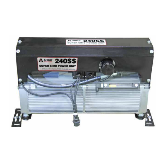
Electrically driven, truck mounted, 10,500 PSI (720 bar) twin pump
hydraulic power unit for simultaneous operation of two rescue tools.
SAFETY MANUAL for AMKUS
RESCUE SYSTEMS
4201 Montdale Drive, Valparaiso, IN 46383-4098 USA
800-592-6587 • 219-548-5000 • Fax 219-476-1669
LAA-001 April 15, 2016 Rev00
LAA-001
(motor and pump) used in this power
Manual: 240SS
Super Simo Power Unit
SECTION 1. IDENTIFICATION
P
o r
d
u
t c
N
a
m
e
Manufacturers of suppliers details
S
D
S
R
e
q
u
e
t s
Customer Service
Emergency telephone number
S
i p
I l l
f n
r o
m
t a
o i
n
Health Information
Recommend use of the chemical and restrictions on use
R
e
c
o
m
m
e
n
d
e
d
U
SECTION 2. HAZARDS IDENTIFICATION
GHS Classi cation
Not a hazardous substance or mixture
GHS Label element
H
a
z
a
d r
p
c i
o t
g
a r
m
S
g i
n
l a
w
o
d r
H
a
z
a
d r
S
a t
e t
m
e
Precautionary statements
Prevention:
Response:
Storage:
Disposal:
Other hazards which do not result in classi cation
Prolonged or repeated skin contact without proper cleaning can clog the pores of the skin resulting in disorders
such as oil acne/folliculitis.
Used oil may contain harmful impurities.
High-pressure injection under the skin may cause serious damage including local necrosis.
Not classi ed as ammable but will burn.
The classi cation of this material is based on OSHA HCS 2012 criteria.
Under normal conditions of use or in a foreseeable emergency, this product does not meet the de nition of
a hazardous chemical when evaluated according to the OSHA Hazard Communication Standard, 29 CFR
1910.1200.
AMKUS RESCUE SYSTEMS
MADE IN USA • www.amkus.com
©Copyright Amkus Rescue Systems, Inc. 2014-2016
SAFETY DATA SHEET
AMKUS MV1 HYDRAULIC FLUID
unit.
4201 Montdale Drive, Valparaiso, IN 46383-4098 USA
800-592-6587 • 219-548-5000 • Fax 219-476-1669
SAFETY DATA SHEET
According to OSHA Hazard Communication
Standard, 29 CFR 1910.1200
A
M
K
U
S
M
V
1
H
Y
D
R
A
U
L
C I
F
L
U
D I
AMKUS RESCUE SYSTEMS, INC.
4201 Montdale Drive
Valparaiso, IN 46383-4098 USA
2
1
9
5 -
4
8
5 -
0
0
0
8
0
0
4 -
2
4
9 -
3
0
0
C
H
E
M
T
R
E
C
s
e
H
y
d
a r
u
c i l
l i o
s
N
o
h
a
z
a
d r
y s
m
b
l o
e r
q
i u
e r
d
N
o
s
g i
n
l a
w
o
d r
n
s t
P
H
Y
S
C I
A
L
H
A
Z
A
R
D
: S
Not classi ed as a physical hazard under GHS criteria.
HEALTH HAZARDS:
Not classi ed as a health hazard under GHS criteria.
ENVIRONMENTAL HAZARDS:
Not classi ed as an environmental hazard under GHS criteria.
No precautionary phrases.
No precautionary phrases.
No precautionary phrases.
No precautionary phrases.
4201 Montdale Drive, Valparaiso, IN 46383-4098 USA
800-592-6587 • 219-548-5000 • Fax 219-476-1669
LAA-004 December 8, 2016 Rev04
LAA-004
LAP-012 July 16, 2018 Rev01
Advertisement
Table of Contents

Related Manuals for Amkus Super Simo 240SS


Summary of Contents for Amkus Super Simo 240SS
- Page 1 This manual does NOT address operation or servicing of AMKUS Rescue Systems. Only competent rescue tool repair technicians Health Information are quali ed to repair AMKUS equipment. This manual should be available to all personnel involved with AMKUS equipment. Recommend use of the chemical and restrictions on use...
-
Page 2: Table Of Contents
6. Failure to follow these guidelines may result in death, burns or other severe injury. Fire and Emergency Manufacturers and Service Association FEM SA P.O. Box 147, Lynnfi eld, MA 01940 • www.FEMSA.org ©Copyright AMKUS Rescue Systems, Inc. 2018 LAP-012 July 16, 2018 Rev01... -
Page 3: Meaning Of Safety Signal Words
• Energizing electrical connections and wiring exposed during service creates ignition and shock hazards. • Always wear safety glasses when servicing, or testing Amkus rescue equipment. Obtain Level 3 service technician training before servicing Amkus rescue equipment. Do not touch electrical connections before you fi rst ensure that power has been disconnected. -
Page 4: Specifications
AMKUS uses another industry fi rst Variable Frequency Drives to regulate electrical requirements. This infi nitely customizable control system is set up to require only 5 amps of current at start up. Unlike other electric power units, the 240SS increases electrical power as the pressure increases through the use of a Programmable Logic Controller (PLC). -
Page 5: Overall Dimensions
2.2 OVERALL DIMENSIONS ©Copyright AMKUS Rescue Systems, Inc. 2018 LAP-012 July 16, 2018 Rev01... -
Page 6: Part Identification
Power Unit Receiver Reel Pressure Reel Return Reel Return Reel Pressure Sight Gauge Drain Plug Heat Exchanger Outlet Power Plug Oil Filter Vent Cap Reservoir Fill Cap Heat Exchanger Inlet ©Copyright AMKUS Rescue Systems, Inc. 2018 LAP-012 July 16, 2018 Rev01... -
Page 7: Screen Identification
The I/O screen shows the states of each input and output in real time. This screen is most helpful for troubleshooting a system. Runtime Screen The runtime screen shows total hours of use on each motor. ©Copyright AMKUS Rescue Systems, Inc. 2018 LAP-012 July 16, 2018 Rev01... -
Page 8: Wiring Identification
4 - OIL/TEMP SENSORS (LVTEMP) 5 - 12VDC IN (12 IN) 6 - 12VDC OUT (12 OUT) 7 - MOTOR 1 (M1) 8 - MOTOR 2 (M2) 9 - 208/240VAC IN (POWER) ©Copyright AMKUS Rescue Systems, Inc. 2018 LAP-012 July 16, 2018 Rev01... -
Page 9: Protective Clothing
AMKUS equipment may cause operational problems, equipment failure, or denial of warranty claims. Normally, AMKUS equipment is prepared and serviced by your dealer prior to delivery. If, however, you have decided to place the equipment into service yourself, please review the following instructions carefully. - Page 10 fi ll cap and fi ll the hydraulic fl uid reservoir until the sight gauge is completely full. Replace the black vent cap and the red reservoir fi ll cap. ©Copyright AMKUS Rescue Systems, Inc. 2018 LAP-012 July 16, 2018 Rev01...
- Page 11 7. The heat exchanger supply utilizes a check valve. The fl ow direction can be determined by the arrow stamped on the If AMKUS standard couplers are being used, be sure the check valve. Connect this hose to an installer provided #8 pressure line has a male coupler at the end of the reel.
-
Page 12: Getting Started
6.0 GETTING STARTED 6.1 INITIAL START-UP 1. Connect the hose reel hoses together before starting the 2. Using a hex-key wrench, remove 4 corner screws system. Remove the VFD cover. ©Copyright AMKUS Rescue Systems, Inc. 2018 LAP-012 July 16, 2018 Rev01... - Page 13 8. Press the physical or digital blue V1 button to activate No. 2. The screen should indicate Motor No. 2 is running. Valve No. 1. The screen should indicate Valve No. 1 is open. ©Copyright AMKUS Rescue Systems, Inc. 2018 LAP-012 July 16, 2018 Rev01...
- Page 14 Pressure Line 1. To verify which hose is the pressure hose, remove both 2. If AMKUS standard couplers are being used, place the couplings from the end of the hoses and place the hose male coupler on the pressure line and the female coupler ends in a bucket.
-
Page 15: Operating Instructions
6. V2 Valve 2 Switch – Press to activate control valve for V2 circuit. Press again to turn control valve off . 8.0 TROUBLESHOOTING GUIDE Any problem not resolved by the following suggestions may require you to contact your local dealer or AMKUS Rescue Systems for further guidance. -
Page 16: Routine Maintenance
Allow the hydraulic fluid to drain completely. Clean and reinstall the drain plug. Replace the filter. Fill the hydraulic fluid reservoir with new AMKUS MV1 fluid. Reinstall the fill plug/vent cap. Cycle rescue tools several times to purge air from the hydraulic hoses.
Need help?
Do you have a question about the Super Simo 240SS and is the answer not in the manual?
Questions and answers