Advertisement
Quick Links
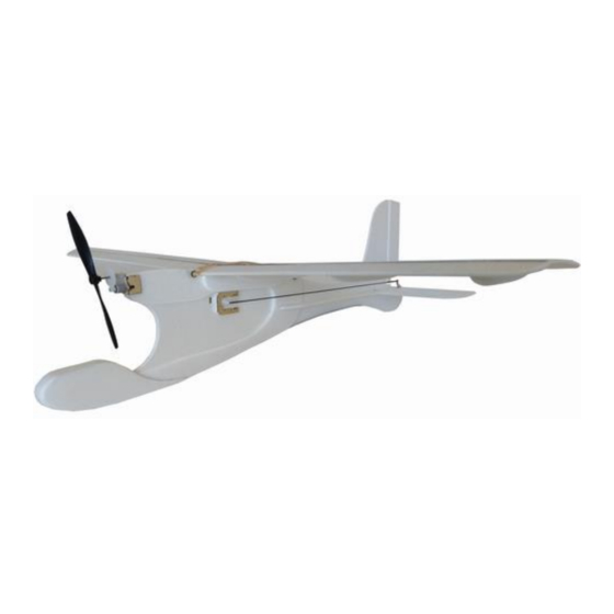
(Build Instructions)
Specifications
* Wingspan: 56cm
* Length: 50.5cm
* Flying Weight: 44 grams
* Channels: 3 (Rudder Elevator Throttle)
* Suggested Receiver: 4Ch Micro
* Motor: 7mm GearDrive (Supplied)
* Prop: GWS 4040 (Supplied)
Included in Airframe Kit
* Airframe Parts
* Geardrive, motor and prop
* Wooden Wing Braces
* Wooden Servo Mounts
* Carbon Struts
* Control Horns and Linkages / Pushrods
* Sandpaper
* Double Sided Mounting Tape
* Rubber Bands
Needed to Complete
* Hot Glue Gun
* Epoxy Glue
* UHU Expanded Polystyrene Glue (link)
* Hobby Knife
* Pliers to cut carbon rod
* Ruler (preferably steel)
* Blenderm Hinge Tape (link)
* Masking Tape or Household Pins
* Soldering Iron to heat the heat shrink
* Sanding Block
* Micro Screwdriver
* Battery Charger and Batteries
* Transmitter, Receiver and Servos
(see website for suggested RC setup)
Advertisement

Related Manuals for MicronWings Student Flyer Lite


Summary of Contents for MicronWings Student Flyer Lite
- Page 1 (Build Instructions) Specifications * Wingspan: 56cm * Length: 50.5cm * Flying Weight: 44 grams * Channels: 3 (Rudder Elevator Throttle) * Suggested Receiver: 4Ch Micro * Motor: 7mm GearDrive (Supplied) * Prop: GWS 4040 (Supplied) Included in Airframe Kit * Airframe Parts * Geardrive, motor and prop * Wooden Wing Braces * Wooden Servo Mounts...
- Page 2 Before You Start This airframe has been designed with school students and first time indoor flyers in mind. The build process is simple, but some careful sanding of the parts is necessary. Follow the instructions below for a trouble-free build process. Two main types of glue are required for this build and each type of glue has its specific purpose.
- Page 3 The tail surfaces and matching control surfaces where they meet need to be cut at an angle on one side to allow them to pivot. To do this, place a metal ruler on top of the surface flush with the edge and press down as you cut at a 30 degree angle back underneath the ruler.
- Page 4 An example of the completed surface The wings will form a V shape when glued together as indicated by the plywood wing struts. So we need to sand the ends of the wings to have a “VERY SLIGHT” angle. This angle only needs to be about 2 degrees as shown below so just a few rubs of the sandpaper is adequate.
- Page 5 Sand the three foam sections under the wing where the wings join to take the ridge off and flatten the surface there a little. Glue these two sets of pieces together as shown in the photo. Glue these pieces under the wings as shown.
- Page 6 Must be flush with top Glue in place the two side pieces. For these, just apply the glue to the side piece and spread it out thin. Then align it with the main centre piece of the fuselage. If you place it on very gently without pressing it down, it will be able to be moved a little to get it in the correct position.
- Page 7 Glue the battery covers to either side of the nose section of the fuselage. Put a very small amount of UHU Expanded Polystyrene Glue on the longer flat carbon strip and some down the middle of the fuselage as well. Allow the glue to dry well (about 15 minutes) and then attach the carbon strip as shown.
- Page 8 Glue in the tailplane checking that it is horizontal Glue the horizontal body parts onto the body and tailplane. Slide them back to fill any gap between them and the horizontal stabiliser. Reinforce the joint with some Blenderm hinge tape top and bottom.
- Page 9 Sand the ends of the round wooden pegs to round the ends off. Then insert them into the airframe in front and behind the wings. Fill these two holes up with Hot Glue to secure the pegs in place. Glue the round supports in place as well with UHU Expanded Polystyrene glue.
- Page 10 Check if the servos need to be reversed on your transmitter settings and centre all trims. Use a ruler to make sure the control surfaces are level with the horizontal and vertical stabilizers. Use some pins or wrap some masking tape around the ends of the pivot joint to hold the control surface level.
- Page 11 Airframe Overview Video Flight Video Flight Video – In the Playground Copyright © MicronWings 2019: All rights reserved. This manual is for personal use only. No unauthorized copying or digital distributing permitted without permission from MicronWings.
Need help?
Do you have a question about the Student Flyer Lite and is the answer not in the manual?
Questions and answers