Advertisement
Quick Links
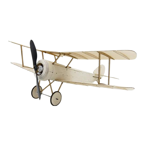
Sopwith Pup
(Build Instructions)
Specifications
Wingspan: 38cm
Length: 29cm
Flying Weight: 46grams
Channels: 3 (Rudder Elevator Throttle)
Suggested Receiver: 4Ch Micro
Motor: 7mm Geared Motor
Airframe Kit
(Included Contents)
* Airframe Covering Parts (balsa)
* Airframe Skeleton (hardwood)
* Carbon pushrods
* Wheels and rubber tyre rings
* Fine sand paper
* Control linkages
* Decals
Needed to Complete
* Thick CA Glue
* Micro Phillips Head Screwdriver
* Long nose fine pliers
* Hobby Knife
* Ruler
* Household Pins
* Hobby Masking or Other Tape
* Tweezers
* Small Screwdriver
* Felt pen
* Patience
* Keen Eyesight
* Steady Hands
* Receiver Transmitter Charger Battery
* Motor and Propeller
(see instructions for suggested RC gear setup)
Battery Options
The Nanotech 300mah 1S battery is
recommended for best balance.
If using the Nanotech 160mah or similar
battery, you will also need to add some
ballast to the nose.
Advertisement

Related Manuals for MicronWings Sopwith Pup


Summary of Contents for MicronWings Sopwith Pup
- Page 1 Sopwith Pup (Build Instructions) Specifications Wingspan: 38cm Length: 29cm Flying Weight: 46grams Channels: 3 (Rudder Elevator Throttle) Suggested Receiver: 4Ch Micro Motor: 7mm Geared Motor Airframe Kit (Included Contents) * Airframe Covering Parts (balsa) * Airframe Skeleton (hardwood) * Carbon pushrods...
- Page 2 Before You Start This airframe has been designed to fit together easily with all components precision drilled and CNC cut from high quality balsa and paulownia wood. However, you will be working with very small components, so you will need patience and keen eyesight. We recommend working in a very well lit area and taking a break between stages to rest the eyes and hands.
- Page 3 Additional Parts...
- Page 4 Before starting you may wish to lightly sand down all the flat surfaces of the parts if you want to have a smooth finish. It’s easier to do this initially, especially in areas such as the wings where ribs will get in the way of sanding when complete.
- Page 5 Construct the circular mounting frame and screw in the control system mount. This is temporary and just holds everything in place while the rest of the frame is being constructed and is drying. Set these 4 parts aside for the next step Note Orientation –...
- Page 6 Then glue in place the rear most part with the two protrusions each side. Once again use the 4 braces put aside earlier to hold this square while drying. Then go ahead and glue those 4 parts in place. Ensure that the second hole in from either side is clear of glue as another part needs to slot in there in the next step.
- Page 7 Attach the part you have just made to the hardwood frame. Ensure all parts are glued at 90 degrees angles. Set aside to dry. Note the orientation of this part when gluing on the rear fuselage frame to make sure you glue these two pieces together the correct way.
- Page 8 Use a sharp hobby knife to cut out these panels. Then bend the bottom plate where shown. Score and bend Cut panels out Glue on the bottom plate. Glue down the sides to meet flush and tape with modelling tape if needed.
- Page 9 Score and bend the tail piece up to match the body line. Attach the tail skid. Look from the back and make any adjustments to the body alignment while gluing. Also cut out the bottom hatch plate. Some scrap wood can be used to glue across the hatch on the inside surface to strengthen it.
- Page 10 Next remove the parts below to make the cowl. Be careful to remove the parts with the stepped edges in one piece as shown here. These pieces are used as a template to position the other cowl pieces before being cut away later. Start by gluing in the magnets as shown. Magnets Glue the parts in place as shown below.
- Page 11 The other three magnets need to be inserted in the holes in the fuselage. However you must take care to align them the right way. First attach the magnets to the ones in the cowl and with a black felt pen mark the side facing you and ensure that side of the magnet is orientated the same when it is glued into the fuselage hardwood frame.
- Page 12 Next we will attach the ribs to the upper wings. The upper wings are the ones which do not have the long cut out pieces near the wing root. Note that as in the image to the left, we only need 3 ribs per wing.
- Page 13 Glue in the ribs taking note that the two ribs with the cut outs go closest to the wing root. Also, note that the holes used to glue on the wing braces are directly in line with a rib. After gluing in that rib, turn the wing over and clear out any glue from the wing brace slots.
- Page 14 Now glue on the central wing section and the wings. Ensure that the wings match smoothly with the top surface of the inner wing section. You can use some thin model masking tape to tape the two surfaces together to keep them level with each other. Also smear some glue on the joint line under the wing where the two wing parts join.
- Page 15 Screw the wheel struts together as shown here. Then screw the wheel struts in place to the airframe. The bent section is toward the front of the airframe and the screw head near the wheel is on the inner side, while the screw heads near the fuselage are on the outer side.
-
Page 16: Important Note
You may wish to add a piece between the wheel and the undercarriage frame as well (which is not shrunk) to act as a spacer. Cut the carbon axel to size with a hobby knife. A small amount of glue on the end only will also help hold it in place. - Page 17 Next build the motor mount. There are two options for powering this model – a brushed motor or a brushless motor. See below for how to build the motor mount for each option. MicronWings suggests using a brushed motor setup, and in this manual we will detail the suggested setup for a brushed motor.
- Page 18 If using a brushed motor, MicronWings suggests using a Gearbox 7mm Twin Drive Horizontally Opposed Base Mount. This motor’s mounting holes align with the mounting holes in the motor mount supplied with the kit. Gearbox 7mm Twin Drive Horizontally Opposed Base Mount...
- Page 19 Radio Gear It’s now time to install your radio gear and servos. Note that this kit does not include receiver, servos, battery, motor, propeller, charger or connectors. The information below is simply a guideline for setting up the system. The airframe is designed to accomoadate 1.7 gram 5320 SH servos. These servos will screw in neatly to the frame.
- Page 20 The list of products below is suggested to complete the setup shown here. 4Ch DSM2 / DSMX Receiver with 2A ESC Receiver 24R6CLV11 DSM2 (The recommended receiver option for this model) (A good option if you prefer a brick type Rx instead) Servo 5320 Black SH Micro Connectors 2mm Round 2 Pin (Most 5320 servos come with Molex 1.27mm connectors.
- Page 21 Feed the control rods through the fuselage and connect them to the servos. Remember the control horn on the right should be controlled by the servo on the left and so on. Be sure to turn on your transmitter and receiver and center the servo arms and trims on the transmitter before you do this.
- Page 22 RC gear and servos without first undoing the control linkages near the control surfaces. You can now cut away the balsa parts which are holding the control surfaces in place. Then test your system to make sure it is all functioning correctly.
- Page 23 The longer screw is attached as shown in the image below and the supplied lead weight wrapped around it to add more weight to the nose. Note that even with the suggested 300mah battery you will still need this additional ballast weight. This is because this is a true scale model and the nose is relatively short.
- Page 24 A sample flight video. Take-off and Landing Video 01 Take-off and Landing Video 02 Copyright © MicronWings 2017: All rights reserved. This manual is for personal use only. No unauthorized copying or digital distributing permitted without permission from MicronWings.
Need help?
Do you have a question about the Sopwith Pup and is the answer not in the manual?
Questions and answers