Advertisement
Quick Links
Isolating Transducer
IME-AIA-11Ex-Hi/24VDC
Short description
• Intrinsically safe powering of
transmitters and isolated transmission
of analog signals
• Input 4...20 mA
• Output 4...20 mA, short-circuit protected
• Galvanic isolation between input and
output
• Intrinsically safe input circuit Ex ia
• Application area according to
ATEX: II (1) GD, II 3 G
• Approved for installation in zone 2
• HART
®
communication
• Transmission characteristic 1:1
Terminal confi guration (Fig. 2)
3, 4
Intrinsically safe input circuit 4...20 mA
10, 9
Output circuit 4...20 mA
14, 13 Power supply
12, 11 Power supply looped in
Connection via cage-clamp terminals:
Connection profi le 0,75 mm
2
...1,5 mm
wire, 0,5 mm
2
...1 mm
2
with wire sleeves.
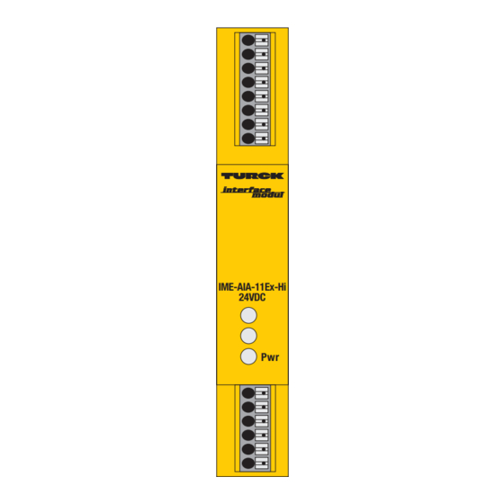
LED indications (Fig. 1 + 2)
Pwr
green
power on
Fig. 1 Front view
IME-AIA-11Ex-Hi
24VDC
Pwr
Functions
Galvanically isolated connection of measuring
two wire transducers by meaning of standard
analog signals 0/4...20 mA from hazardous
area into safe area.
Special conditions for application in zone 2
For installation in zone 2 the device must be
installed in a housing which complies with the
requirements of EN 60079-15 with a minimum
protection degree of IP54 according to
IEC/EN 60529.
With mounting in zone 2 the connecting and
disconnecting of energized non energy limited
circuits is only permitted in non-explosive
atmosphere.
The application of litz-wires recommends the
fi xation of cable ends with wire sleeves.
2
blank
Fig. 2 Circuit diagram
HART
®
+ 3
?
– 4
4...20 mA
Mounting and Installation (Fig. 4 + 5)
The device is suited for snap-on clamps for
DIN rail mounting (EN 60715).
Devices of the same type may be mounted
directly next to each other. It must be ensured
that heat is conducted away from the device.
Mounting and installation must be carried out in
accordance with the applicable regulations.
The operator is responsible for compliance with
the regulations.
The device must be protected against dust,
dirt, moisture and other environmental infl u-
ences as well as against strong electromagnetic
emissions.
It should also be protected against the risks of
mechanical damaging, unauthorized access
and incidental contact.
All installations must be carried out observing
the regulations of EMC protection.
The cable junction via cage-clamp terminals is
shown in Fig. 4.
10 +
4…20 mA
9, 11, 13 –
Pwr
12, 14 +
24 VDC
GN
Fig. 5 Dimension drawing
Fig. 4 Cable junction
110
112
18
Advertisement

Subscribe to Our Youtube Channel
Related Manuals for turck IME-AIA-11Ex-Hi/24VDC


Summary of Contents for turck IME-AIA-11Ex-Hi/24VDC
- Page 1 Isolating Transducer IME-AIA-11Ex-Hi/24VDC Mounting and Installation (Fig. 4 + 5) Short description Functions The device is suited for snap-on clamps for • Intrinsically safe powering of Galvanically isolated connection of measuring DIN rail mounting (EN 60715). transmitters and isolated transmission...
- Page 2 Turck devices are obtainable via the Internet (www.turck.com). Further infor- mation on explosion protection is available on request. Subject to change without notice © Hans Turck GmbH & Co. KG 2008 • Hans Turck GmbH & Co. KG Witzlebenstraße 7 45472 Mülheim/Ruhr...
Need help?
Do you have a question about the IME-AIA-11Ex-Hi/24VDC and is the answer not in the manual?
Questions and answers