Table of Contents
Advertisement
Quick Links
Advertisement
Table of Contents

Related Manuals for L-Acoustics SB18 IIi


Summary of Contents for L-Acoustics SB18 IIi
- Page 1 SB18 IIi owner's manual (EN)
- Page 2 Document reference: SB18 IIi owner's manual (EN) version 1.0 Distribution date: March 30, 2021 © 2021 L-Acoustics. All rights reserved. No part of this publication may be reproduced or transmitted in any form or by any means without the express written consent of the publisher.
-
Page 3: Table Of Contents
KARAIIi-RIGBAR..........................13 M-BARi............................16 KARAIIi-FIXBRACKET........................17 Front screens............................18 Mechanical safety.............................21 Loudspeaker congurations..........................23 SB18 IIi in standard conguration......................23 SB18 IIi in cardioid conguration......................24 Rigging procedures............................25 General principles...........................25 Flying..............................26 Flying an array with KARAIIi-BUMP....................26 Flying an array with KARAIIi-RIGBAR....................31 Adding a pullback with KARAIIi-RIGBAR..................33... - Page 4 Securing a screen........................... 44 Connection to LA amplied controllers........................ 46 Cabling schemes.............................47 Corrective maintenance............................. 49 Introduction.............................49 Tools............................49 SB18 IIi..............................50 Specications..............................57 APPENDIX A: Recommendation for speaker cables....................63 APPENDIX B: Specications for custom rigging systems..................64...
-
Page 5: Safety
Respect the Working Load Limit (WLL) of third party equipment. L-Acoustics is not responsible for any rigging equipment and accessories provided by third party manufacturers. Verify that the Working Load Limit (WLL) of the suspension points, chain hoists and all additional hardware rigging accessories is respected. - Page 6 This system is intended for use by trained personnel for professional applications. As part of a continuous evolution of techniques and standards, L-Acoustics reserves the right to change the specications of its products and the content of its documents without prior notice.
-
Page 7: Introduction
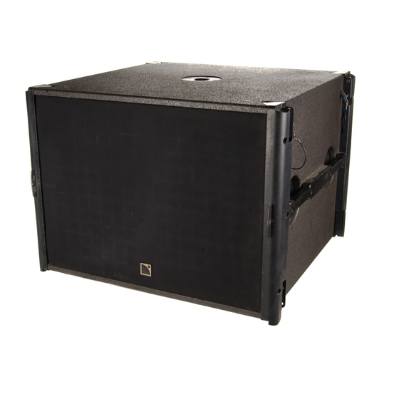
Introduction SB18 IIi SB18 IIi is a compact subwoofer designed to extend the bandwidth of the Kara IIi system in installation applications. It features one high-excursion, direct-radiating 18" transducer mounted in a dual bass-reex tuned enclosure. SB18 IIi can be coupled mechanically and acoustically with Kara IIi to reinforce contour and extend bandwidth to 32 Hz. -
Page 8: System Components
Refer to the LA2Xi / LA4X / LA8 / LA12X owner's manual for detailed instructions about the whole cabling scheme, including modulation cables and network. Rigging elements KARAIIi-BUMP Flying frame for vertical deployment of Kara IIi and SB18 IIi KARAIIi-RIGBAR Rigging bar and pullback for Kara IIi and SB18 IIi M-BARi... -
Page 9: Loudspeaker Cables
Rigging elements CLAMP250 M-BARi KARAIIi-RIGBAR KARAIIi-BUMP SB18IIi-SCREEN Rigging plates SB18IIi-LINK SB18IIi-ENDLINK KARAIIi-FIXBRACKET Rigging plates for SB18 IIi End rigging Fastening brackets for plates for SB18 IIi Kara IIi and SB18 IIi SB18 IIi owner's manual (EN) version 1.0... -
Page 10: Electro-Acoustical Description
OUT 3 OUT 4 Connectors SB18 IIi 1 × 4-point terminal block with push-in connection Internal pinout for L-Acoustics subwoofers terminal block points IN + IN - Transducer connectors LF + LF - SB18 IIi owner's manual (EN) version 1.0... -
Page 11: Rigging System Description
Rigging system description SB18 IIi SB18 IIi is the dedicated subwoofer for Kara IIi. SB18 IIi is compatible with two types of rigging kits: standard rigging plates (SB18IIi-LINK) end rigging plates (SB18IIi-ENDLINK) SB18 IIi features ten M6 inserts on each side:... -
Page 12: Rigging Elements
KARAIIi-BUMP KARAIIi-BUMP is a rigging frame for ying arrays of SB18 IIi. KARAIIi-BUMP can be used as the main lifting accessory for ying vertical arrays of SB18 IIi with one or two lifting points. SB18 IIi owner's manual (EN) version 1.0... -
Page 13: Karaiii-Rigbar
WLL 3.25 t (two provided). Four holes are available to secure M-BARi in position A or B, to provide additional pickup points. Refer to M-BARi (p.16). 5 6 7 8 9 FRONT KARAIIi-RIGBAR KARAIIi-RIGBAR is a rigging bar for pullback congurations of SB18 IIi arrays. SB18 IIi owner's manual (EN) version 1.0... - Page 14 Secured at the bottom of the array, KARAIIi-RIGBAR can be used as a pullback with another KARAIIi-RIGBAR as the main lifting accessory. With KARAIIi-RIGBAR as the main lifting accessory, SB18IIi-ENDLINK is required on the top enclosure. KARAIIi-RIGBAR can be secured at the front for an initial positive site angle. SB18 IIi owner's manual (EN) version 1.0...
- Page 15 Maximum limit with CLAMP250. CLAMP250 has a WLL (Working Load Limit) of 250 kg / 550 lb. It can support an array of up to 5 SB18 IIi. For an hybrid array, check the total weight of the array in Soundvision.
-
Page 16: M-Bari
Rigging system description M-BARi The M-BARi extension bar can be secured on KARAIIi-BUMP to extend the site angle capability of SB18 IIi arrays. It can be used as a front or rear extension, with two possible positions each (A or B). -
Page 17: Karaiii-Fixbracket
Rigging system description KARAIIi-FIXBRACKET KARAIIi-FIXBRACKET is a set of four fastening brackets for SB18 IIi. The enclosure is secured to KARAIIi-FIXBRACKET using the slotted hole. Secure KARAIIi-FIXBRACKET at the bottom of an array to improve stability and to anchor it to the ground. -
Page 18: Front Screens
Rigging system description KARAIIi-FIXBRACKET can also be used to mount up to two SB18 IIi under the ceiling. KARAIIi-FIXBRACKET must be secured to the supporting xture with four M10 screws. Fasteners for ceiling-mounting Select screw length and anchors applicable to the ceiling properties. - Page 19 The screens are secured on top of the rigging plates with four M6×35 Torx screws which replace the grill screws. The grill screws can be removed through the rigging plates. The screens are equipped with tabs to hold the grill in place when securing the screen on the enclosure. SB18 IIi owner's manual (EN) version 1.0...
- Page 20 Rigging system description SB18IIi-SCREEN can be secured to the back of SB18 IIi when used in cardioid conguration. The cable(s) can be passed through a cutout on the screen side. SB18 IIi owner's manual (EN) version 1.0...
-
Page 21: Mechanical Safety
Mechanical safety Flown congurations The SB18 IIi rigging system complies with 2006/42/EC: Machinery Directive. It has been designed following the guidelines of BGV-C1. 2006/42/EC: Machinery Directive species a safety factor of 4 against the rupture. The own deployments described in this manual achieve a safety factor of 4 or more. - Page 22 Soundvision calculations are based on usual environmental conditions. A higher safety factor is recommended with factors such as extreme high or low temperatures, strong wind, prolonged exposition to salt water, etc. Always consult a rigging specialist to adopt safety practices adapted to such a situation. SB18 IIi owner's manual (EN) version 1.0...
-
Page 23: Loudspeaker ConGurations
Loudspeaker congurations SB18 IIi in standard conguration Deployed in a standard conguration, an SB18 IIi system operates with an omnidirectional directivity pattern over the nominal bandwidth of the SB18 IIi enclosure. The [SB18_60] and [SB18_100] factory presets provide the subwoofer system with an upper frequency limit at 60 Hz and 100 Hz respectively in order to optimize the acoustic coupling with a main full-range system. -
Page 24: Sb18 Iii In Cardioid ConGuration
Deployed in a cardioid conguration, an SB18 IIi system produces a rear SPL rejection. The deployment consists of an array of four SB18 IIi with one element turned towards the rear (reversed). Refer to the Cardioid Conguration technical bulletin for more information. -
Page 25: Rigging Procedures
This introduction provides general principles applicable for all congurations. Safety Rigging screws Only use the rigging screws provided by L-Acoustics. Do not use the placeholder screws for rigging. Tightening screws Do not fully tighten the screws unless instructed to do so. -
Page 26: Flying
Rigging plates for SB18 IIi Risk of falling objects Verify that no unattached items remain on the product or assembly. Secondary safety Use available holes on the rigging accessories to implement a secondary safety. SB18 IIi owner's manual (EN) version 1.0... - Page 27 Rigging procedures Assembly Procedure 1. Prepare all SB18 IIi needed for the array. a) Remove the placeholder screws. b) Secure SB18IIi-LINK on the enclosures. Do not secure the bottom screws, except on the last enclosure of the array. SB18 IIi owner's manual (EN) version 1.0...
- Page 28 Rigging procedures 2. Secure KARAIIi-BUMP on top of a rst SB18 IIi. Optionally, secure M-BARi on KARAIIi-BUMP to extend the site angle capability. Use the provided rigging axes, nuts, and safety pins. Tighten all the screws on KARAIIi-BUMP. Apply a torque of 5 N.m.
- Page 29 Rigging procedures b) Lower the array until the enclosures can be assembled. The rigging plates of the bottom enclosure overlap the rigging plates of the top enclosure. c) Link the enclosures with rigging screws. SB18 IIi owner's manual (EN) version 1.0...
- Page 30 Apply a torque of 5 N.m. 5 N.m e) Raise the array. 5. Repeat step (p.28) until all SB18 IIi are assembled. 6. Check that all screws are present and tightened, and raise the array. What to do next •...
-
Page 31: Flying An Array With Karaiii-Rigbar
Verify that no unattached items remain on the product or assembly. Secondary safety Use available holes on the rigging accessories to implement a secondary safety. Assembly Procedure 1. Prepare the rst enclosure. a) Remove the relevant placeholder screws. SB18 IIi owner's manual (EN) version 1.0... - Page 32 Maximum limit with CLAMP250. CLAMP250 has a WLL (Working Load Limit) of 250 kg / 550 lb. It can support an array of up to 5 SB18 IIi. For an hybrid array, check the total weight of the array in Soundvision.
-
Page 33: Adding A Pullback With Karaiii-Rigbar
2. Remove the bottom screw from the rear rigging plates on each side. 3. Secure KARAIIi-RIGBAR at the rear of the enclosure with M6×40 Torx screws. Apply a torque of 5 N.m. 5 N.m SB18 IIi owner's manual (EN) version 1.0... - Page 34 Rigging procedures 4. Secure a shackle to KARAIIi-RIGBAR and lift it with an additional motor. SB18 IIi owner's manual (EN) version 1.0...
-
Page 35: Ceiling-Mounting
Kara IIi and SB18 IIi plates for SB18 IIi Fasteners for ceiling-mounting Select screw length and anchors applicable to the ceiling properties. Model the array in Soundvision and check the loads on rigging in the Mechanics view. SB18 IIi owner's manual (EN) version 1.0... - Page 36 Model the array in Soundvision and check the loads on rigging in the Mechanics view. 778 mm / 30.6 in Ø 12 mm / 0.5 in 2. Prepare an SB18 IIi. a) Remove the placeholder screws. SB18 IIi owner's manual (EN) version 1.0...
- Page 37 This step requires three operators. Hold the enclosure at the bottom until the rigging plates are secured. 3. Lift SB18 IIi and secure it to the slotted holes on KARAIIi-FIXBRACKET with rigging screws. Apply a 5 N.m. torque. 5 N.m 4.
- Page 38 Secure SB18IIi-LINK on the enclosure. This step requires three operators. Hold the enclosure at the bottom until the rigging plates are secured. 6. Lift SB18 IIi and secure it under the rst one with rigging screws. SB18 IIi owner's manual (EN) version 1.0...
- Page 39 Rigging procedures 7. Tighten all the screws. Apply a 5 N.m. torque. 5 N.m 8. Check that all screws are secured and tightened. What to do next • Securing a screen (p.44) SB18 IIi owner's manual (EN) version 1.0...
-
Page 40: Stacking
Kara IIi and SB18 IIi plates for SB18 IIi Fasteners for ceiling-mounting Select screw length and anchors applicable to the ceiling properties. Model the array in Soundvision and check the loads on rigging in the Mechanics view. SB18 IIi owner's manual (EN) version 1.0... - Page 41 Procedure 1. Secure KARAIIi-FIXBRACKET to the ground using M10 screws. 778 mm / 30.6 in Ø 12 mm / 0.5 in 2. Prepare up to four SB18 IIi. a) Remove the placeholder screws. SB18 IIi owner's manual (EN) version 1.0...
- Page 42 On the last enclosure of the array, secure SB18IIi-ENDLINK instead. Risk of crushing injury Keep ngers away from underneath the enclosure. 3. Secure SB18 IIi to the slotted holes on KARAIIi-FIXBRACKET. Tighten the bottom screws. Apply a 5 N.m. torque. 5 N.m...
- Page 43 Risk of crushing injury Keep ngers away from underneath the enclosure. 4. Secure additional SB18 IIi (equipped with rigging plates) on top of the rst one. Adjusting the gap between stacked enclosures Place a wedge or a lever between the two enclosures to align the rigging with the inserts.
-
Page 44: Securing A Screen
2. If the enclosure is not equipped with rigging plates (standalone, ground-stacked enclosure), stick the washers on the screen xing tabs. Risk of bending xing tabs Always use the self-sticking washers for securing screens when there are no rigging plates on the enclosure. SB18 IIi owner's manual (EN) version 1.0... - Page 45 Only use the provided M6×35 Torx screws to secure the screens. 3. Secure the screen to the enclosure. If SB18 IIi is reversed (cardioid conguration), connect the cables to the enclosure before securing SB18IIi- SCREEN. Pass the cables through the cutout on the screen side.
-
Page 46: Connection To La AmpliEd Controllers
LA8 can drive up to two SB18 IIi per output, but no more than six per controller at high level. SB18 IIi owner's manual (EN) version 1.0... -
Page 47: Cabling Schemes
Refer to the LA2Xi owner's manual for more information on output congurations. Terminal block output (SE) 4− 3− 2− 2.5 mm² cables 1− Terminal block output (BTL) 4− 3− 2.5 mm² cables 2− 1− One-channel speakON output custom cable 2.5 mm² cable 1+/1- SB18 IIi owner's manual (EN) version 1.0... - Page 48 Connection to LA amplied controllers Two-channel speakON output custom cable 2.5 mm² cable 1+/1- 2+/2- 2.5 mm² cable SB18 IIi owner's manual (EN) version 1.0...
-
Page 49: Corrective Maintenance
® ® tools. The Maintenance Toolcase includes tools manufactured by FACOM , Fluke , Tohnichi, ABUS and Würth. All third-party trademarks, registered trademarks, or product names are the property of their respective owners. SB18 IIi owner's manual (EN) version 1.0... -
Page 50: Sb18 Iii
SB18 IIi SB18 IIi exploded view In order to operate, follow the order outlined here. Each assembly refers to the corresponding Disassembly/Reassembly (D/R) procedure and the necessary repair kit. LF SPEAKER GRILL KR HPBC182 SB18 IIi owner's manual (EN) version 1.0... - Page 51 Tools • torque screwdriver • T30 Torx bit Repair kit KR HPBC182 KR 18" loudspeaker SB18(i) / SB18 IIi ×14 S221 M6×35 Torx Exploded view For safety reasons, always use the new screws and spare parts provided in the KR.
- Page 52 Corrective maintenance D/R - LF speaker Tools • torque screwdriver • T30 Torx bit • 5 mm hex bit Repair kit KR HPBC182 KR 18" loudspeaker SB18(i) / SB18 IIi ×1 ×8 ×14 ×4 S100054 S221 100689 18" speaker - 8 ohms M6×30 hex...
- Page 53 Corrective maintenance 2. Remove the speaker screws. 5 mm 3. Remove the speaker from the enclosure and disconnect the speaker cables. SB18 IIi owner's manual (EN) version 1.0...
- Page 54 Corrective maintenance 4. If the speaker gaskets are damaged, remove and replace them. SB18 IIi owner's manual (EN) version 1.0...
- Page 55 If no new screws are available, use blue threadlocker. Procedure 1. Connect the speaker cables and position the speaker in the enclosure. 2. Secure the speaker. Gradually tighten the screws following a star pattern. 5 N.m 5 mm SB18 IIi owner's manual (EN) version 1.0...
- Page 56 Corrective maintenance 3. Secure the plate. Gradually tighten the screws following a star pattern. SB18 IIi owner's manual (EN) version 1.0...
-
Page 57: SpeciCations
Pantone 426 C pure white RAL 9010 custom RAL code on special order IP55 Peak level at 1 m under half space conditions using pink noise with crest factor 4 (preset specied in brackets). SB18 IIi owner's manual (EN) version 1.0... - Page 58 Specications SB18 IIi dimensions 701 mm / 27.6 in 701 mm / 27.6 in SB18 IIi owner's manual (EN) version 1.0...
- Page 59 M-BARi dimensions 954 mm / 37.6 in KARAIIi-RIGBAR specications Description Rigging bar and pullback for Kara IIi and SB18 IIi 2 × Ø12 mm shackles WLL 1 t Weight (net) 4.8 kg / 11 lb Material...
- Page 60 Specications KARAIIi-BUMP specications Description Flying frame for vertical deployment of Kara IIi and SB18 IIi 2 × Ø19 mm shackles WLL 3.25 t Weight (net) 21 kg / 46 lb Material high grade steel with anti-corrosion coating KARAIIi-BUMP dimensions 707 mm / 27.8 in...
- Page 61 Specications KARAIIi-FIXBRACKET specications Description Fastening brackets for Kara IIi and SB18 IIi Weight (net) 0.5 kg / 1.1 lb Material high grade steel with anti-corrosion coating KARAIIi-FIXBRACKET dimensions 35 mm / 1.4 in 60 mm / 2.4 in Ø 6.9 mm / 0.27 in 6.9 mm / 0.27 in...
- Page 62 CLAMP250 dimensions 167 mm / 6.6 in 103 mm / 4.1 in SB18IIi-SCREEN specications Description Acoustically transparent front screen for SB18 IIi Weight (net) 2.7 kg / 6 lb SB18IIi-SCREEN dimensions 714 mm / 28.1 in 97 mm / 3.8 in...
-
Page 63: Appendix A: Recommendation For Speaker Cables
8 Ω load 4 Ω load 2.7 Ω load Use the more detailed L-Acoustics calculation tool to evaluate cable length and gauge based on the type and number of enclosures connected. The calculation tool is available on our website: https://www.l-acoustics.com/en/installation/tools/... -
Page 64: Appendix B: SpeciCations For Custom Rigging Systems
699.8 + 3 mm / 27.51 + 0.12 in 700.3 mm / 27.55 in 660.9 mm / 25.98 in 4 x M6 inserts per side SB18 IIi Weight without rigging plates • SB18 IIi: 48 kg / 106 lb SB18 IIi owner's manual (EN) version 1.0... - Page 65 Adapt the length of the screws according to the thickness of the sheet. • Prevent bolts from loosening (threadlocker, spring washer...) Threaded inserts • Maximum loads: • Maximum tensile load: 1160 N • Maximum shear load: 4250 N • Recommended torque: 5 N.m. SB18 IIi owner's manual (EN) version 1.0...
- Page 66 L-Acoustics 13 rue Levacher Cintrat - 91460 Marcoussis - France +33 1 69 63 69 63 - info@l-acoustics.com www.l-acoustics.com...
Need help?
Do you have a question about the SB18 IIi and is the answer not in the manual?
Questions and answers