
Related Manuals for Metso JAMESBURY Wafer-Sphere Series


Summary of Contents for Metso JAMESBURY Wafer-Sphere Series
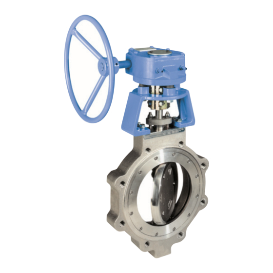
- Page 1 Wafer-Sphere® Butterfly Valve Model C 2 1/2” - 24” (DN65 - 600) Class 150 & 300 Installation, Maintenance and Operating Instructions...
-
Page 2: Table Of Contents
These instructions provide information about safe handling and operation of the valve. If you require additional assistance, please contact the manufacturer or manufacturer’s representative. Addresses and phone numbers are printed on the back cover. See also www.metso.com/valves for the latest documentation. SAVE THESE INSTRUCTIONS! IMO 1/18... -
Page 3: General
IF YOU HAVE ANY QUESTIONS CONCERNING THE USE, APPLICATION those listed in (Table 1). OR COMPATIBILITY OF THE VALVE WITH THE INTENDED SERVICE, CONTACT METSO FOR MORE INFORMATION. TABLE 1 Maximum Allowable Differential Offset Shaft Design... -
Page 4: Valve Markings
IMO-308 EN Valve Markings WAFER-SPHERE BUTTERFLY VALVES WAFER DESIGN The valve has an identification plate attached to the valve body (see Figure 4). Square drive in disc closed position. Identification Plate Blade drive in disc Figure 4 closed position. Identification plate markings: Trim material Valve catalog code Seat Material... -
Page 5: Transportation And Storage
IMO-308 EN Installing in the pipeline WARNING: WHEN HANDLING THE VALVE OR VALVE/ACTUATOR ASSEMBLY, TAKE ITS WEIGHT INTO ACCOUNT! WARNING: NEVER LIFT THE VALVE OR VALVE/ACTUATOR ASSEMBLY BY THE THE VALVE SHOULD BE TIGHTENED BETWEEN FLANGES USING ACTUATOR, POSITIONER, LIMIT SWITCH OR THEIR PIPING. PLACE APPROPRIATE GASKETS AND FASTENERS COMPATIBLE WITH LIFTING DEVICES SECURELY AROUND THE VALVE BODY. -
Page 6: Valve Insulation
Metso recommends inspecting valves at least every five (5) years. The inspection and maintenance frequency depends on the actual application and process condition. -
Page 7: Actuated Valve
IMO-308 EN Actuated Valve It is generally most convenient to detach the actuator and its auxiliary devices before removing the valve from the pipeline. If the valve package is small or if it is difficult to access, it may be more practical to remove the entire assembly. -
Page 8: Seat Replacement Standard Valves
IMO-308 EN Seat Replacement Standard Valves TABLE 2 Insert Screw Torque Table (FT•LBS Unless Otherwise Specifield) Numbers in ( ) refer to items shown in (Figure 15). Torque Carbon Steel Screw Size FT•LBS N•m FT•LBS (N•m) 50 IN•LBS (6) 23 IN•LBS (3) After removing the valve from the line, place it on a 1/4”... -
Page 9: Shaft Seal Replacement
IMO-308 EN Carefully clean the gasketing surfaces with a suitable A body seal (40) is required between the seat tail and body as shown in (Figure 10). The valve uses a graphite solvent. They should be free of all grooves and scratches. -
Page 10: Valve Disassembly
IMO-308 EN Remove the shaft (4). NOTE: When removing the shaft Remove C-shaped retainer ring (47) from the shaft. and freeing the disc, be careful not to scratch the Remove the compression ring (9). sealing surface of the disc. Remove the disc (3) and upper and lower thrust Remove the old shaft seal (8) segments. -
Page 11: Testing The Valve
IMO-308 EN 4.10 Testing the Valve toward the bonnet, place the disc in the waterway and slide the shaft through the shaft bore in the disc. Place the lower thrust bearing (64) below the disc, slide the WARNING: shaft through and into the lower shaft bearing (6). Use caution to prevent damage to the shaft bearings and WHEN PRESSURE TESTING, EXERCISE CAUTION AND MAKE SURE ALL EQUIPMENT USED IS IN GOOD WORKING CONDITION AND... -
Page 12: Manual Handles
IMO-308 EN 11. Repressurize the valve and check the leakage. If valve Lift the ratchet plate up and rotate it 180 degrees. Do not still leaks, repeat step 10. If leakage cannot be stopped, turn it upside down. adjust the actuator stop so that leakage is minimized. 12. -
Page 13: Actuator Mounting Instructions
IMO-308 EN Caution: An actuator should be remounted on the TABLE 4 valve from which it was removed. The actuator must be Actuator readjusted for proper open and close position each time it Quadra-Powr® IMO-31, 32 is remounted. ST-50 IMO-22 ST-60, 90, 115, 17SMS IMO-23 Caution: The linkage has been designed to support the... -
Page 14: Repair Kits
Valves sent to the service center without MSDS datasheet(s) will not be accepted. For further information on spare parts and service or assistance visit our web-site at www.metso.com/valves. NOTE: When ordering spare parts, always include the following information: Valve catalog code from identification plate, b. - Page 15 IMO-308 EN PARTS LIST EXPLODED VIEW AND PARTS LIST ITEM PART NAME Valves Without Cover Plates Body Insert Graphite TEFLON ® Disc (FIRE-TITE) (Standard) Shaft Seat Shaft Bearing Spacer Shaft Seal Compression Ring Compression Plate Disc Pin Stud DIRECTION OF SEALS (8) Nameplate Drive Screw Cap Screw...
- Page 16 IMO-308 EN PARTS LIST EXPLODED VIEW AND PARTS LIST ITEM PART NAME Valves With Cover Plates Body Insert TEFLON Graphite Disc (FIRE-TITE) (Standard) Shaft Seat Shaft Bearing Spacer Shaft Seal Compression Ring Compression Plate Disc Pin Stud DIRECTION OF SEALS (8) Nameplate Drive Screw Cap Screw...
- Page 17 IMO-308 EN STEP 3B Tighten these to Screw Size Torque FT•LBS (N•m) 5/16” 25 (34) 3/8” 40 (54) 1/2” 90 (122) 5/8” 165 (224) STEP 3A Tighten these until bracket sits firmly on valve NO PLAY COUPLING STEP 3C Tighten these to Screw Size Torque FT•LBS (N•m) 3/8”...
- Page 18 IMO-308 EN WAFER-SPHERE REPAIR KITS MODEL C Size Soft Seat FIRE-TITE Wafer Wafer 2-1/2” (DN 65) 815 RKW-470 RKW-471 2-1/2” (DN 65) 830 RKW-470 RKW-471 3” (DN 80) 815 RKW-352 RKW-358 RKW-364 RKW-370 3” (DN 80) 830 RKW-352 RKW-358 RKW-364 RKW-370 4”...
- Page 19 Therefore, some of the situations in which the valves are used are outside the scope of this manual. If you have any questions concerning the use, application or compatibility of the valve with the intended service, contact Metso for more information.
- Page 20 IMO-308 EN Subject to change without prior notice. Metso Corporation Töölönlahdenkatu 2, PO Box 1220, 00100 Helsinki, Finland Tel. +358 20 484 100 http://contact.metso.com/ Neles Finland Inc. Vanha Porvoontie 229, P.O. Box 304, FI-01301 Vantaa, Finland. Tel. +358 20 483 150. Fax +358 20 483 151...
Need help?
Do you have a question about the JAMESBURY Wafer-Sphere Series and is the answer not in the manual?
Questions and answers