
Subscribe to Our Youtube Channel
Related Manuals for Metso Jamesbury 4000 B


Summary of Contents for Metso Jamesbury 4000 B
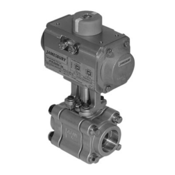
- Page 1 Series 4000 Model B 3-Piece Ball Valves with ISO Bonnet 1/2" – 2" (DN 15 – 50) Standard Bore, 1/2" – 1-1/2" (DN 15 – 40) Full Bore Installation, Maintenance and Operating Instructions...
- Page 2 IMO-210EN Table of Contents GENERAL ........3 1.1 Warning .
- Page 3 IMO-210EN 3. Remove or protect the handle or actuator from weld GENERAL splatter or arc strikes. This instruction manual contains important information regarding the installation, operation and troubleshooting 4. Weld by applying a recommended 1/8" (3.2 mm) max. for the Jamesbury 1/2" – 2" (DN 15 – 50) Standard Bore, 1/2" weld bead per pass around each end cap.
- Page 4 IMO-210EN 6. Turn the stem (4) so that the valve is fully closed. TABLE 2 Remove the inner body seals (6) and outer body seals Hex. Head Cap Screw Torque (18) and the seats (5). NOTE: On those valves with Valve Size Torque IN•LBS Torque N•m...
- Page 5 IMO-210EN Surface A FIRE-TESTED NON FIRE-TESTED 1/16" (1.6 mm) Interlock Figure 3 3. Holding the stem in place from the bottom, install the 11. Swing the entire body assembly back into the properly stem seal (8) and the compression plate (20). For valves aligned and interlock position between the body caps, with graphite stem seals (8), install upper stem bearing being careful not to scratch the body seals.
- Page 6 IMO-210EN PARTS LIST ITEM PART NAME EXPLODED VIEW AND PARTS Body Body Cap Ball Stem Seat Inner Body Seal Secondary Stem Seal Stem Seal † Stem Bearing Stem Bearing Handle Nut Handle Outer Body Seal Shakeproof Washer Compression Plate 22** Identification Tag 23** Pop Rivet...
- Page 7 IMO-210EN TABLE 4 Service Kits Valve Size – Full Port Size Shown in ( ) 1/2" (1/2") 3/4" 1" (3/4") 1-1/4" (1") 1-1/2" (1-1/4") 2" (1-1/2") Valve Size DN 15 (DN 15) DN 20 DN 25 (DN 20) DN 32 (DN 25) DN 40 (DN 32) DN 50 (DN 40) PTFE Seats...
- Page 8 IMO-210EN Subject to change without prior notice. Metso Automation Inc. Europe, Vanha Porvoontie 229, P.O. Box 304, FI-11301 Vantaa, Finland, Tel. +358 20 483 150, fax +358 20 483 151 North America, 44 Bowditch Drive, P.O. Box 8044, Shrewsbury, Massachusetts, 01545-8044, USA, Tel. +1 508 852 0200, fax +1 508 852 8172 South America, Av.
Need help?
Do you have a question about the Jamesbury 4000 B and is the answer not in the manual?
Questions and answers