
Subscribe to Our Youtube Channel
Related Manuals for Metso Jamesbury Wafer-Sphere 8000 Series


Summary of Contents for Metso Jamesbury Wafer-Sphere 8000 Series
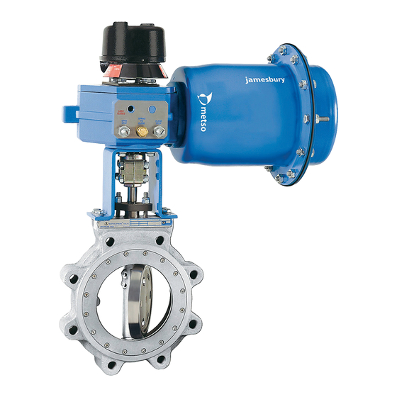
- Page 1 Wafer-Sphere® Butterfly Valves 3"-12" Series 8000, 8100, 8200 & 8300 Installation, Maintenance and Operating Instructions...
-
Page 2: Table Of Contents
These instructions provide information about safe handling and operation of the valve. If you require additional assistance, please contact the manufacturer or manufacturer's representative. Addresses and phone numbers are printed on the back cover. See also www.metso.com/valves for the latest documentation. SAVE THESE INSTRUCTIONS! Subject to change without notice. -
Page 3: Description
IMO-13 DESCRIPTION The Jamesbury® Wafer-Sphere valve is a butterfly valve of high performance design. IMPORTANT NOTE: Maximum shut-off pressure rating depends on the materials chosen. Refer to the tag attached to each valve for this rating. Do not use a valve at service conditions that exceed the rating of the tag. -
Page 4: Positive Stop Feature
IMO-13 PRECAUTIONS SAFETY FIRST! FOR YOUR SAFETY, TAKE THE FOLLOWING PRECAUTIONS BEFORE REMOVING THE VALVE FROM THE LINE, OR BEFORE ANY DISASSEMBLY: 1. WHAT'S IN THE LINE? BE SURE YOU KNOW WHAT FLUID IS IN THE LINE. IF THERE IS ANY DOUBT, DOUBLE-CHECK WITH THE PROPER SUPERVISOR. -
Page 5: Installation
IMO-13 INSTALLATION MAINTENANCE I. WAFER-SPHERE VALVES with TFE or other POLYMERIC General SEAT Routine maintenance consists of tightening down the In general, for full pressure rating, all polymeric seated compression plate periodically to compensate for seal Wafer-Sphere butterfly valves including Fire-Tite valves wear. - Page 6 IMO-13 Figure 6 Exploded View...
-
Page 7: Shaft Packing Replacement
IMO-13 12. Set the handle or actuator stops as described in the Valve Parts SETTING ADJUSTMENTS Section. Do not install and ITEM NO. NO. REQ'D. PART NAME tighten flanges on a newly reseated valve until the BODY handle or actuator stops are properly set. Incorrect disc INSERT positioning may cause damage to a new seat when the DISC... -
Page 8: Valve Assembly
IMO-13 3. Remove the shaft packing compression hardware as wire brush. CAUTION: use care to keep contamination detailed in Steps 1-5 in the SHAFT PACKING out of the valve. REPLACEMENT section. The packing material itself can 9. Install the upper bearing spacer (41) (on all valves be more easily removed after the shaft has been except 8"... -
Page 9: Actuator Mounting
IMO-13 Figure 7 Figure 8 ACTUATOR MOUNTING Change of Actuator Quadrant Original mounting of actuators is not covered in this doc- If it is necessary to orient the actuator in a different quad- ument because of the wide variety of possible actuators. If rant (Figures 9 and 10): an actuator is to be added to the valve, see the Actuator 1. -
Page 10: Setting Adjustments
IMO-13 Figure 9 Figure 10 tor drive shaft and valve stem. Failure to tighten snug- SETTING ADJUSTMENTS ly will cause the shaft and disc to be pushed downward away from optimum seat contact when final tighten- Setting Stops (valve in the line) ing is accomplished. -
Page 11: Handle Stop (Fig. 9)
IMO-13 Setting Handle Stop (Fig. 8) screw, tighten the closed (shut) stop set screw acorn nut. 1. Loosen the two hex head cap screws (H6) and the two nuts (15) clamping the ratchet plate to the valve. 9. Cycle the valve open and closed, with full air pressure, three times. -
Page 12: Fire-Tite Wafer-Sphere Valves
IMO-13 FIRE-TITE WAFER-SPHERE VALVES Seat Replacement 1. After removing the valve from the line, place it on a bench and cycle it open. Take care not to damage the sealing edge of the valve disc. 2. Remove the insert screws (21) and the insert (2), see (Fig. - Page 13 IMO-13 6 inches (handling will be difficult). Do not start tape over an insert screw hole. e. Upon reaching the starting point, lap tape not more than 1/8" and cut lapping tape with a sharp blade. f. Compress the tape on the insert by rolling (use cylinder, Fig.
- Page 14 IMO-13...
- Page 15 IMO-13...
- Page 16 IMO-13 Subject to change without prior notice. Metso Automation Inc. Europe, Vanha Porvoontie 229, P.O. Box 304, FI-01301 Vantaa, Finland, Tel. +358 20 483 150, fax +358 20 483 151 North America, 44 Bowditch Drive, P.O. Box 8044, Shrewsbury, Massachusetts, 01545-8044, USA, Tel. +1 508 852 0200, fax +1 508 852 8172 South America, Av.
Need help?
Do you have a question about the Jamesbury Wafer-Sphere 8000 Series and is the answer not in the manual?
Questions and answers