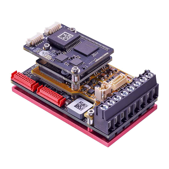
Summary of Contents for SYNAPTICON SOMANET
- Page 1 Wiring instructions Documentation v 4.7. | Built 2021-04-13 © 2021 Synapticon GmbH...
-
Page 2: Table Of Contents
1.3.4.2 Analog input resistance 1.3.4.2.1 Differential 1.3.4.2.2 Single-ended 1.3.4.3 Attaching a voltage divider 1.3.5 EtherCAT port 1.4 Connector details and mating parts numbers © 2021 Synapticon GmbH | Daimlerstraße 26 | D-71101 Schönaich Documentation v 4.7. | Built 2021-04-13 2/17... -
Page 3: Wiring Instructions
Installation Guide / Wiring instructions 1 Wiring instructions 1.1 Overview of connectors Power supply, phases and brake Encoders and IO Connector types and mating parts numbers © 2021 Synapticon GmbH | Daimlerstraße 26 | D-71101 Schönaich Documentation v 4.7. | Built 2021-04-13 3/17... -
Page 4: Power Supply, Phases And Brake
Phase D - Brake output 0-48 V PWM Ground Main Power Supply 12-48 V Optional Logic Ground * Optional Logic Supply 12-24 V ** © 2021 Synapticon GmbH | Daimlerstraße 26 | D-71101 Schönaich Documentation v 4.7. | Built 2021-04-13 4/17... -
Page 5: Notes About Choosing The Supply Voltage
Due to voltage drop from power supply to the servo drive is it not recommended to supply the servo drive at absolute minimal voltages. If your system does not run at 12 V, increasing this value slightly may be necessary. © 2021 Synapticon GmbH | Daimlerstraße 26 | D-71101 Schönaich Documentation v 4.7. | Built 2021-04-13 5/17... -
Page 6: Using A Pelv Or Selv Power Supply
In case you are running several servo drives behind a contactor, please use an uni-directional TVS diode on each drive because of the inductances of the wiring. © 2021 Synapticon GmbH | Daimlerstraße 26 | D-71101 Schönaich Documentation v 4.7. | Built 2021-04-13 6/17... -
Page 7: Connecting A Brake
Ground of the 48V supply to the pin 5 of the Main Supply connector if they fit in there. © 2021 Synapticon GmbH | Daimlerstraße 26 | D-71101 Schönaich Documentation v 4.7. | Built 2021-04-13 7/17... - Page 8 Hardware Manuals / SOMANET Node / SOMANET Node rev. E.1 / Installation Guide / Wiring instructions Important Please make sure the servo drive is properly grounded. You can connect the heatsink to ground. © 2021 Synapticon GmbH | Daimlerstraße 26 | D-71101 Schönaich Documentation v 4.7. | Built 2021-04-13 8/17...
-
Page 9: Encoders And Io
** This is a 5 V supply that can provide up to 250 mA for external use. The supply is protected against short to ground and keeps the current below 400 mA in a continuous short. © 2021 Synapticon GmbH | Daimlerstraße 26 | D-71101 Schönaich Documentation v 4.7. | Built 2021-04-13 9/17... - Page 10 *** This is a 5 V supply that can provide up to 250 mA for external use. The supply is protected against short to ground and keeps the current below 400 mA in a continuous short. © 2021 Synapticon GmbH | Daimlerstraße 26 | D-71101 Schönaich Documentation v 4.7. | Built 2021-04-13 10/17...
-
Page 11: Encoder Port 3 / Digital Io
*** This is a +5 V supply that can provide up to 250 mA for external use. The supply is protected against short to ground and keeps the current below 400mA in a continuous short. © 2021 Synapticon GmbH | Daimlerstraße 26 | D-71101 Schönaich Documentation v 4.7. | Built 2021-04-13 11/17... -
Page 12: Analog In
10 V **** Analog Input 3 - Differential ±5 V Analog Input 3 + Differential ±5 V Analog Input 4 - Differential ±5 V © 2021 Synapticon GmbH | Daimlerstraße 26 | D-71101 Schönaich Documentation v 4.7. | Built 2021-04-13 12/17... -
Page 13: Analog Input Specification
Any voltage out of this range in,N between the negative input damages the analog input’s circuitry. pin and GND. 27.2kΩ Internal input resistance Error Error in ticks © 2021 Synapticon GmbH | Daimlerstraße 26 | D-71101 Schönaich Documentation v 4.7. | Built 2021-04-13 13/17... -
Page 14: Single-Ended
GND. circuitry. 20.4kΩ Internal input resistance Error Error in ticks 1.3.4.2 Analog input resistance 1.3.4.2.1 Differential 1.3.4.2.2 Single-ended © 2021 Synapticon GmbH | Daimlerstraße 26 | D-71101 Schönaich Documentation v 4.7. | Built 2021-04-13 14/17... -
Page 15: Attaching A Voltage Divider
A voltage divider is needed when the Analog In needs to be calibrated. This is required for adjusting the measuring range when using a temperature sensor. The following pins of Analog In can be used: 1 .3.5 EtherCAT port © 2021 Synapticon GmbH | Daimlerstraße 26 | D-71101 Schönaich Documentation v 4.7. | Built 2021-04-13 15/17... - Page 16 Differential transmit pair, negative line Shield Differential receive pair, positive line Differential receive pair, negative line * Pin 1 is on left © 2021 Synapticon GmbH | Daimlerstraße 26 | D-71101 Schönaich Documentation v 4.7. | Built 2021-04-13 16/17...
-
Page 17: Connector Details And Mating Parts Numbers
** Housing only. Please ensure to only use shielded cables for EtherCAT communication! Please also check out our dedicated EtherCAT node to PC cable which is specifically designed for this purpose. © 2021 Synapticon GmbH | Daimlerstraße 26 | D-71101 Schönaich Documentation v 4.7. | Built 2021-04-13 17/17...


Need help?
Do you have a question about the SOMANET and is the answer not in the manual?
Questions and answers