Table of Contents
Advertisement
Quick Links
Advertisement
Table of Contents

Subscribe to Our Youtube Channel
Related Manuals for getAir EASY


Summary of Contents for getAir EASY
- Page 1 EASY Control unit Installation and operating instructions v 1.0_06/2017...
- Page 2 All rights reserved. These instructions have been compiled with the greatest care. Nevertheless, the publisher will accept no liability for any damage resulting from missing or incorrect details therein. We reserve the right to make partial or entire changes to these instructions without prior announcement.
-
Page 3: Table Of Contents
Table of content 1 General remarks ..........................4 2 Installation preparations ........................6 2.1 EASY control unit components ....................6 2.2 Dimensions ..........................7 2.3 Required tools ..........................7 3 Installation ............................8 3.1 Connection and wiring ......................9 3.2 Wall installation ........................11 4 Operating the system ........................12 4.1 Controls .............................12... -
Page 4: General Remarks
1 General remarks Though its contents have been checked for consistency with the described hard- and soft- ware, deviations cannot be ruled out, meaning that no guarantee of complete consistency can be given. This documentation is updated on a regular basis. Necessary corrections and useful addenda will always be included in subsequent versions. - Page 5 The following list contains descriptions of the symbols and terms used in these instructions: This hazard symbol warns about the Caution danger of injury. Hazard symbol This hazard symbol warns about the Electricity danger of electrocution. This warning symbol indicates Warning symbol Please note important information.
-
Page 6: Installation Preparations
2 Installation preparations Before starting installation, please check that all components are present, as otherwise it will not be possible to complete the installation. 2.1 EASY control unit components Article name Position Content Number Control unit with backplate and hexagon... -
Page 7: Dimensions
2.2 Dimensions Name Width (mm) Height (mm) Depth (mm) Ø (mm) Control unit Cover Control knob 2.3 Required tools The following equipment is needed to install the control unit: • Screwdriver • Wrench • Hammer and chisel for cable ducts / slits •... -
Page 8: Installation
3 Installation Up to four fan units can be connected to one control unit. The control unit can be installed anywhere on a wall at normal height. 3-pole cables (preferably LiYY cables) are required. To ensure adequate power, the cable length between the control unit and fan unit must not exceed 100 m. -
Page 9: Connection And Wiring
3.1 Connection and wiring All electrical work must be performed by a qualified electrician. Make sure that all wiring is done correctly. Fan 1 Fan 3 + 12V + 12V RED PUR BLU Power +12V supply black BLU PUR RED + 12V + 12V Fan 2... - Page 10 To connect the control unit to the fan units, a 3-pin plug must be connected to the cable. The plug must be wired as shown. Cable colour Labelling Function fan unit +12V Purple Blue INCORRECT WIRING CAN CAUSE DAMAGE TO THE FAN UNIT.
-
Page 11: Wall Installation
3.2 Wall installation Connect the power supply and the fans in accordance with the diagrams. Insert the power supply into the pattress box and fix the control unit‘s backplate onto the wall. Insert the cover on the potentiometer, making sure that it is straight. Use a wrench to screw the hexagon nut to the control unit. -
Page 12: Operating The System
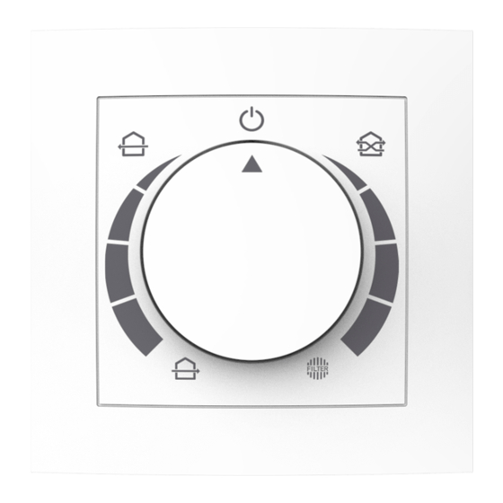
4 Operating the system 4.1 Controls ON/OFF For turning the system on/off. Activates heat recovery mode. The currently selected fan speed is shown Eco-Mode on the scale. Activates full-blast mode. The currently selected fan speed is shown on Full-blast mode the scale. -
Page 13: Modi
4.2 Modi Eco-Mode The system changes the airflow direction once every 50 - 70 seconds, dependent on the selected fan speed, thereby ensuring optimal heat recovery. Full-blast mode The system runs in just one direction, allowing a room to be thoroughly ventilated. Heat recovery is not available in this mode. -
Page 14: Technical Data
5 Technical data Mains connection [V] 230 AC / 50-60 Hz Operating voltage [V] 12 DC SELV Power consumption < 0,5 Software class Permissible operating temperature [°C] 0 ... 40 Type of protection IP 40 Contamination level Dimensions [mm] 80 x 80 x 18 (WxHxD) Colour White Conformity... -
Page 15: Maintenance
Disposal recommendations for all components: Component Material Disposal Control unit Electrical components Electronics recycling Backplate Aluminium Metal recycling Collection of recyclable Cover materials Collection of recyclable Control knob materials 7 Maintenance Regularly wipe the surfaces of the cover and the knob with a dry microfibre cloth. 8 Warranty The same warranty terms and conditions as for the ventilation system apply.
Need help?
Do you have a question about the EASY and is the answer not in the manual?
Questions and answers