
Related Manuals for Vogt TUBE-ICE 10TA


Summary of Contents for Vogt TUBE-ICE 10TA
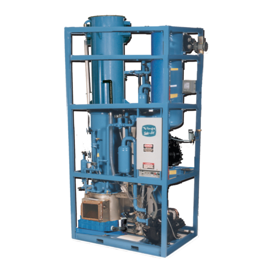
- Page 1 10TA TUBE-ICE ® MACHINE (Includes model P18FXT) Manual Part Number 12A4171M08 Revision 3 Service Manual...
- Page 2 Form MUST be completed and returned to the factory promptly after the official start-up. Product Registration Form is located in the Owners Packet or can be found online at www.vogtice.com/registration.htm. ® Please return to: VOGT ICE , LLC Suite #19 1000 W. Ormsby Ave. Louisville, KY 40210...
- Page 3 ® ® ® ® VOGT ICE , LLC, located in Louisville, Kentucky since 1880. Sales - (800) 959-8648 Service - (502) 635-3000 Parts - Your Local Distributor Call your local distributor first for all of your parts and service needs.
- Page 4 ® Vogt ® Tube-Ice Machines Installation, Service Manual and Parts Catalog #12A4171M08 10TA Model...
-
Page 5: Table Of Contents
Safety Valves ................................. 2-1 Machine Room ................................2-1 Storage (prior to installation and start-up) ........................2-2 Vogt Model Nomenclature, FIGURE 2-1 ........................2-2 3. INSTALLING YOUR TUBE-ICE MACHINE Piping and Drain Connections, TABLE 3-1 ......................... 3-1 Water Cooled Condenser Connections, FIGURE 3-1 ....................3-2 Cooling Tower ................................ - Page 6 10TA Service Manual TABLE OF CONTENTS Page No. 4. HOW YOUR TUBE-ICE MACHINE WORKS Principle of Operation ..............................4-1 Freeze Period ................................. 4-2 Harvest Period ................................4-2 Piping Nomenclature ..............................4-2 Water Cooled Piping Schematic, FIGURE 4-1 ......................4-3 Air-Cooled Piping Schematic, FIGURE 4-2 ........................4-4 5.
- Page 7 10TA Service Manual TABLE OF CONTENTS Page No. 7. MAINTENANCE (cont) Cutter Gear Reducer Lubrication ........................... 7-7 Preventive Maintenance ..............................7-8 For The Manager ................................7-9 Preventive Maintenance Form ............................7-10 8. TROUBLESHOOTING List Of Symptoms ................................8-1 Machine Won’t Run ..............................8-2, 8-3 Freeze-Up Due To Extended Freezing Period .......................
- Page 8 10TA Service Manual TABLE OF CONTENTS Page No. 9. SERVICE OPERATIONS (cont.) Coresense Protection ..............................9-10 Oil Separator, FIGURE 9-8 ............................9-11 Compressor Crankcase Heater ............................9-11 Control Circuit Protection .............................. 9-11 Thawing Timer, FIGURE 9-9A ............................. 9-12 Thawing Timer ................................9-12 Pump Down ...................................
- Page 9 10TA Service Manual TABLE OF CONTENTS Page No. 11. TABLES AND CHARTS (cont.) Normal Operating Vitals, TABLE 11-6 ......................... 11-4 Recommended Spare Parts List ............................. 11-5 Temperature - Pressure Chart for Common Refrigerants, TABLE 11-7 ................ 11-6 Conversion Factors: English to Metric, TABLE 11-8 ....................11-7 Constants, TABLE 11-9 ..............................
- Page 10 10TA Service Manual TABLE OF CONTENTS BLANK...
-
Page 11: Introduction
1. Introduction ® VOGT ICE , LLC A Brief History Of Our Company. Henry Vogt Machine Co. was founded as a small machine shop in Louisville, Kentucky in 1880. In 1938, Vogt built the first Tube-Ice ® machine and revolutionized the ice-making industry. Our first “sized-ice” machine quickly replaced the old can- ice plants, which required much hard labor and large amounts of floor space for freezing, cutting, and crushing ice by hand. -
Page 12: Important Safety Notice
10TA Service Manual INTRODUCTION Important Safety Notice. This information is intended for use by individuals possessing adequate backgrounds of electrical, refrigeration and mechanical experience. Any attempt to repair major equipment may result in personal injury and property damage. The manufacturer or seller cannot be responsible for the interpretation of this information, nor can it assume any liability in connection with its use. - Page 13 10TA Service Manual INTRODUCTION Safety Symbols & What They Mean. Prior to installation or operation of the Tube-Ice ® machine, please read this manual. Are you familiar with the installation, start-up, and operation of a Tube- machine? Before you operate, adjust or service this machine, you should read this manual, ®...
- Page 14 10TA Service Manual INTRODUCTION THAWING GAS STOP VALVE (90) HEAT EXCHANGER (13) CONTROL PANEL LOW PRESSURE GAGE (1PG) HIGH PRESSURE GAGE (2PG) OIL PRESSURE SWITCH (94) FAN CONTROL HIGH-LOW SWITCH PRESSURE SWITCH (41A) (4PS) HIGH PRESSURE COMPRESSOR TEST CONNECTION LOW PRESSURE TEST CONNECTION LIQUID OUTLET STOP VALVE...
- Page 15 10TA Service Manual INTRODUCTION SAFETY RELIEF FREEZER VALVE (51) CHECK VALVE FREEZER (101) PRESSURE STOP VALVE (69) CONDENSER SUCTION SERVICE ACCUMULATOR CONNECTION (88) (32) FLOAT SWITCH (22) LIQUID RETURN LIQUID FEED STOP VALVE SOLENOID VALVE (91) ("A1" VALVE) (20) HAND EXPANSION VALVE (17)
- Page 16 10TA Service Manual INTRODUCTION SAFETY RELIEF COLD WEATHER VALVE (50) SOLENOID VALVE ("X" VALVE) (53) RECEIVER (15R) RECEIVER SIGHT GLASS (30) SEPARATOR THAWING GAS (14) SOLENOID VALVE ("D" VALVE) (18) RECEIVER DRAIN CUTTER MOTOR VALVE (44) (5M) GEAR REDUCER (5R) 1/2"...
- Page 17 10TA Service Manual INTRODUCTION CONDENSER (15) THAWING GAS HEAT STOP VALVE EXCHANGER (90) (13) LOW PRESSURE GAGE (1PG) CONTROL PANEL HIGH PRESSURE GAGE (2PG) OIL PRESSURE SWITCH (94) HIGH-LOW PRESSURE SWITCH (4PS) COMPRESSOR HIGH PRESSURE TEST CONNECTION LIQUID OUTLET LOW PRESSURE STOP VALVE TEST CONNECTION (KING VALVE)
- Page 18 10TA Service Manual INTRODUCTION FREEZER SAFETY RELIEF VALVE FREEZER (51) PRESSURE STOP VALVE (69) SUCTION ACCUMULATOR (88) FLOAT SWITCH (22) LIQUID RETURN LIQUID FEED STOP VALVE SOLENOID VALVE (91) ("A1" VALVE) (20) HAND EXPANSION VALVE (17) FREEZER REFRIGERANT CHARGING VALVE OIL RETURN (28) STOP VALVE...
- Page 19 10TA Service Manual INTRODUCTION CONDENSER WATER REGULATING VALVE (41) SAFETY RELIEF VALVE (50) RECEIVER (15R) RECEIVER SEPARATOR SIGHT GLASS (14) (30) THAWING GAS SOLENOID VALVE ("D" VALVE) CUTTER MOTOR (18) (5M) RECEIVER DRAIN VALVE (44) GEAR REDUCER 1/2" MPT (5R) MAKE-UP WATER CONNECTION MAKE-UP...
- Page 20 10TA Service Manual 1-10 INTRODUCTION BLANK 4/14/14...
-
Page 21: Receipt Of Your Tube-Ice Machine
The machine was shipped with a full charge of refrigerant stored in the receiver. Visually check all lines for mechanical damage. If a leak is suspected, check all joints with a Halogen Leak Detector. All leaks should be reported to the Vogt Ice, LLC to obtain authorization for repair. CAUTION The approximate weight of the machine is 4900 pounds. -
Page 22: Storage (Prior To Installation And Start-Up)
"NC" - No Condenser "21" - 230-1-60 Product Variation Codes (An alphanumeric designator assigned to specific variations.) "000 or Blank" – Standard Product If unsure of the product code shown on your machine please consult the factory. Figure 2-1 Vogt Model Nomenclature 4/14/14... -
Page 23: Installing Your Tube-Ice Machine
10TA Service Manual ® INSTALLING YOUR TUBE-ICE MACHINE ® 3. Installing Your Tube-Ice Machine WARNING Only service personnel experienced and certified in refrigeration and qualified to work with high voltage electrical equipment should be allowed to install or work ® on this Tube-Ice machine. -
Page 24: Cooling Tower
10TA Service Manual ® INSTALLING YOUR TUBE-ICE MACHINE Water-Cooled Connections Note: Water regulator valve is not installed on condenser when shipped from the factory. Installed water regulator valve on condenser water inlet connection (bottom connection on condenser). Connect the condenser water out line to the top connection on the condenser. 2 1/2”... - Page 25 10TA Service Manual ® INSTALLING YOUR TUBE-ICE MACHINE FIGURE 3-2A Connections and Space Diagram (Air Cooled Machine) 4/14/14...
- Page 26 10TA Service Manual ® INSTALLING YOUR TUBE-ICE MACHINE FIGURE 3-2B Connections and Space Diagram (Water Cooled Machine) 4/14/14...
-
Page 27: Wiring And Electrical Connection Figure 3-3
10TA Service Manual ® INSTALLING YOUR TUBE-ICE MACHINE Wiring and Electrical Connection WARNING Only service personnel experienced in refrigeration and qualified to work with high voltage ® electrical equipment should be allowed to install or work on the Tube-Ice machine. WARNING Refer to TABLE 3-2 below to properly size wiring connections. - Page 28 10TA Service Manual ® INSTALLING YOUR TUBE-ICE MACHINE Phase Check CAUTION DO NOT attempt to start machine without priming pump and insuring proper rotation of both cutter and pump. Refer to FIGURE 3-1 & 3-2 (space diagram) for connection locations. CAUTION Cutter and pump motor rotation are factory synchronized but must be checked at installation.
-
Page 29: Air-Cooled Condenser Installation Instructions
COMPRESSOR WARRANTY WILL NOT BE HONORED. WARNING 1. Use only Vogt approved condensers. Any exceptions to this policy must be obtained in writing from Vogt prior to installation and operation of the ice machine. 2. Outdoor condensers must be installed with vertical air flow. Indoor condensers used for heat recovery may be installed with either horizontal or vertical air flow. - Page 30 Recommended condensers provide the indicated total heat rejection at 90°F ambient, 100°F condensing. Vogt Ice, LLC is not responsible for head pressure problems if other than the recommended condensers are used. For continuous operation at ambient temperature above 105°F, consult the factory about using a larger condenser.
- Page 31 10TA Service Manual ® INSTALLING YOUR TUBE-ICE MACHINE Ice Machine Model 10TA Electrical Frequency, Hz. Recommended Condenser BNHS04A029 Total Heat Rejection (BTU/hr) 427,500 393,300 Fans: Number HP, Each 1 1/2 1 1/2 Total CFM 38,600 38,600 Full Load Amps (FLA): 3 ph., 208/230V, 60 hz.
- Page 32 10TA Service Manual 3-10 ® INSTALLING YOUR TUBE-ICE MACHINE FIGURE 3-4 Condenser Dimensions Machine Bohn Part # Vogt Part # Coil Split P18XT BNHS04A029 12A2115B11 50/50 Note: Condensers listed above are 200/208/230V, 50/60hz. 400/460V, 50/60hz available 4/14/14...
- Page 33 10TA Service Manual 3-11 ® INSTALLING YOUR TUBE-ICE MACHINE Note: Condenser return lines supplied by customer. (check valve supplied by Vogt) FIGURE 3-5 Condenser Field Piping (Cold Weather Valve Kit) 4/14/14...
-
Page 34: Minimum Traps For Discharge Lines, Figure 3-6
10TA Service Manual 3-12 ® INSTALLING YOUR TUBE-ICE MACHINE CONDENSER EQUIVALENT LINE SIZE WORKSHEET Discharge Gas Line O.D. ___________________ Fitting Type Number Used Factor Total Globe Valve (open) Angle Valve (open) 90° Elbow 45° Elbow Feet of Straight Copper Used Total Fitting Factor Total Equivalent Feet Copper Tubing Type “L”... - Page 35 10TA Service Manual 3-13 ® INSTALLING YOUR TUBE-ICE MACHINE Air-Cooled Condenser Wiring FIGURE 3-7 Wiring For BOHN BNHS04A029 with Cold Weather Valve and Four Fans, 50/50 Condenser Split 4/14/14...
- Page 36 VALVE REPLACEMENT SHOULD BE MADE BY PROPERLY TRAINED PERSONNEL ONLY. NOTE: IF RELIEF VALVE DISCHARGES, VALVE MUST BE REPLACED AFTER DISCHARGING BECAUSE SETTING OR SEAT TIGHTNESS MAY BE ALTERED. CONTACT VOGT ICE PARTS DEPARTMENT FOR REPLACEMENT VALVES. PHONE: 502-635-3000 4/14/14...
-
Page 37: Ice Bin Thermostat Sensor
10TA Service Manual 3-15 ® INSTALLING YOUR TUBE-ICE MACHINE Ice Bin Thermostat Sensor (Optional) An electronic ice bin thermostat may be added to automatically cycle machine operation. To assure proper protection for the machine or auxiliary equipment, the sensor of the ice bin thermostat must be located so that ice will contact it when the bin is full (See FIGURE 3-8 for typical mounting bracket). -
Page 38: Programming Electronic Bin Thermostat
10TA Service Manual 3-16 ® INSTALLING YOUR TUBE-ICE MACHINE Programming the Electronic Bin Thermostat The electronic bin thermostat has an LCD readout that displays the temperature in the bin at the sensor. The control has been preset and locked out at the factory to shut the machine down at 38° ° ° ° F and to re-start at 40°... -
Page 39: Installation Review: A Checklist
10TA Service Manual 3-17 ® INSTALLING YOUR TUBE-ICE MACHINE IMPORTANT Be sure to follow the wiring schematic and electrical specification table when incorporating overloads. This is necessary to provide proper protection ® ® ® ® for the Tube-Ice machine and its component parts. IMPORTANT Installation Review: A Checklist. - Page 40 10TA Service Manual 3-18 ® INSTALLING YOUR TUBE-ICE MACHINE BLANK PAGE 4/14/14...
-
Page 41: How Your Tube-Ice Machine Works
10TA Service Manual HOW YOUR TUBE-ICE MACHINE WORKS ® 4. How Your Tube-Ice Machine Works Principle Of Operation. For a detailed description of the functions of each control panel components, see Section 6. Operation of the machine is controlled by “Clean/Off/Ice”, “Start” and “Stop”... -
Page 42: Freeze Period
10TA Service Manual HOW YOUR TUBE-ICE MACHINE WORKS Air-cooled machines have a solenoid valve (53), sometimes referred to as the “X” valve, in the compressor discharge line, and a check valve (101) in the liquid return line to the receiver. These valves prevent the migration of refrigerant when the machine is not operating. -
Page 43: Water Cooled Piping Schematic, Figure 4-1
10TA Service Manual HOW YOUR TUBE-ICE MACHINE WORKS FIGURE 4-1 Water Cooled Piping Schematic 4/14/2014... -
Page 44: Air-Cooled Piping Schematic, Figure 4-2
10TA Service Manual HOW YOUR TUBE-ICE MACHINE WORKS FIGURE 4-2 Air-Cooled Piping Schematic 4/14/2014... -
Page 45: Start-Up And Operation
10TA Service Manual START-UP AND OPERATION Start-Up and Operation Refrigeration System Review The refrigeration system uses R-22 or R-404a refrigerant, a compressor, a refrigerant float switch, expansion valve, a flooded evaporator (freezer), and warm gas defrost. Following the schematic, you see that during the freeze period of the machine’s cycle, the condenser discharge gas leaves the compressor and goes to the condenser where it is condensed into liquid by the removal of heat by either air or water passing through the condenser. - Page 46 10TA Service Manual START-UP AND OPERATION Start-up Checklist. Be sure to complete and return the “Warranty Registration/Start-Up Report” located at the front of the manual. _____ 1. See that water-inlet and outlet connections are attached properly. The water inlet shutoff valves for the water tank and condenser should be open.
-
Page 47: Start-Up Procedure
6. Be sure to observe a minimum of four (4) cycles of ice production to confirm the satisfactory operation of the machine (approximate time for four cycles is 60-80 minutes). Complete the remaining part of the “Warranty Registration/Start-Up Report” upon initial machine start-up and return it to Vogt Ice, LLC. 4/14/14... -
Page 48: Shut-Down Procedure
10TA Service Manual START-UP AND OPERATION Shut-down CAUTION The red “Stop” button should only be used for emergency shutdown. For normal shutdown use the “Clean/Off/Ice” button. CAUTION Set the “Clean/Off/Ice” switch to the “Off” position. Do not use the machine disconnect to stop the machine. -
Page 49: Adding Refrigerant
10TA Service Manual START-UP AND OPERATION Adding Refrigerant CAUTION If it should become necessary to add refrigerant to the system, charging valve (28) is provided for this purpose. Be sure to follow all local and federal regulations regarding the handling of refrigerants and their illegal emission into the atmosphere. - Page 50 10TA Service Manual START-UP AND OPERATION BLANK 4/14/14...
-
Page 51: Control Panel (Cover On), Figure 6-1
10TA Service Manual ELECTRICAL CONTROLS 6. Electrical Controls FIGURE 6-1 Control Panel 4/14/14... - Page 52 10TA Service Manual ELECTRICAL CONTROLS FIGURE 6-2 Control Panel Components (Standard) 4/14/14...
- Page 53 10TA Service Manual ELECTRICAL CONTROLS OPTIONAL POWER MONITOR LOCATED ON BACK OF ENCLOSURE DOOR. SWITCHES LOCATED ON OUTSIDE OF CONTROL PANEL DOOR FIGURE 6-2A Control Panel Door (Standard) and Optional Power Monitor 4/14/14...
-
Page 54: Control Panel Components (Ce & Australian Approved), Figure 6-2B
10TA Service Manual ELECTRICAL CONTROLS FIGURE 6-2B Control Panel Components (CE & Australian Approved) 4/14/14... - Page 55 10TA Service Manual ELECTRICAL CONTROLS Item No. Vogt Part No. Description 12A7518E33UL Aux Trip Indicator, 6A, 1NO / 1NC 12A2117G09 Bin Thermostat (Optional ) Control Circuit Breaker, 6 Amp, 2 Pole (400V & 460V machines 12A7515E22 only) 12A7516E30 Compressor Motor Contactor (72 Amp, 3 Pole) 12A7518E30 Aux.
- Page 56 10TA Service Manual ELECTRICAL CONTROLS Description of Component Function Auxiliary trip indicator for manual motor starters. Switches when cutter or pump motor starter trips. AX – Overload and short circuit protection for control circuit and crankcase heater. (400/460V machines CB2 – only) Provides power to the compressor motor.
- Page 57 10TA Service Manual ELECTRICAL CONTROLS FIGURE 6-3 Control Circuit - Electrical Schematic All Voltages, 50-60 Hz. 4/14/14...
- Page 58 10TA Service Manual ELECTRICAL CONTROLS FIGURE 6-3A 3-Phase Power - Electrical Schematic All Voltages, 50-60 Hz. 4/14/14...
-
Page 59: Compressor Schematic Detail All Voltages, 50-60 Hz., Figure 6-4
10TA Service Manual ELECTRICAL CONTROLS FIGURE 6-4 Compressor Schematic Detail All Voltages, 50-60 Hz. 4/14/14... - Page 60 10TA Service Manual 6-10 ELECTRICAL CONTROLS BLANK 4/14/14...
-
Page 61: Maintenance
10TA Service Manual MAINTENANCE 7. Maintenance ® Ice Making Section. The ice-making section of the Tube-Ice machine should be cleaned at least twice a year (more often if water conditions cause mineral build-up). Use an approved food-grade ice machine cleaner. The water pump is used to circulate the cleaner through the system by setting the “Clean/Off/Ice”... -
Page 62: Sanitizing Procedure
10TA Service Manual MAINTENANCE Sanitizing Procedure 1. After pumping machine down, set “Clean/Off/Ice” selector switch (SS) to the “Off” position. 2. Remove ice from storage area. 3. Shut off water supply and drain water tank (7) by opening drain valve (39). Remove any loose sediment from tank. -
Page 63: Water Distributors
(due to channeling of water), or if some of the ice is opaque, or if there is a noticeable decrease in ice capacity. Vogt Part # Size Ice Number of Tubes... -
Page 64: Water Cooled Condensers
10TA Service Manual MAINTENANCE Water Cooled Condensers Checking Operation. How often condensers need cleaning depends on so many variables that it is impossible to recommend a schedule. Some will seldom need cleaning, others perhaps need cleaning once a year. In rare cases, cleaning is required several times a year. Proper operation of cooling towers will increase the interval between cleaning considerably. -
Page 65: Chemical Cleaning
10TA Service Manual MAINTENANCE Chemical Cleaning. Vogt Ice, LLC makes no recommendation for any particular chemical reparation. The same chemical may not be effective for all situations. CAUTION The following directions and precautions should be observed when cleaning is undertaken. The warranty on condensers is void if they are damaged by improper cleaning tools or methods. -
Page 66: Lubrication
10TA Service Manual MAINTENANCE Flush condenser tubes clear with air, water, or a piece of rag on a stick or wire. In many cases this is all that is required. If the inside surfaces are smooth, even though discolored, further cleaning is not necessary. - Page 67 10TA Service Manual MAINTENANCE An oil pump should be used to force any oil that may be required into the system. Oil may be added to the compressor through the oil separator oil return line fitting on the compressor or the compressor suction service valve.
-
Page 68: Preventive Maintenance
BEFORE REPLACING RELIEF VALVE, REVIEW REQUIREMENTS PER CURRENT LOCAL AND NATIONAL CODE. NOTE: IF RELIEF VALVE DISCHARGES, VALVE MUST BE REPLACED BECAUSE SETTING OR SEAT TIGHTNESS MAY BE ALTERED. CONTACT VOGT ICE PARTS DEPARTMENT FOR REPLACEMENT VALVES. PHONE: 502-635-3000 4/15/14... -
Page 69: For The Manager
10TA Service Manual MAINTENANCE For The Manager Who Depends Upon This Machine For Efficient Operation. “Preventive Maintenance” simply means that you or a delegated employee makes a daily visual check ® of your Tube-Ice machine. Here is what to look for and why: Daily checklist: 1. - Page 70 10TA Service Manual 7-10 MAINTENANCE Note To Manager or Owner: This page is a complete Preventive Maintenance Schedule that should be performed each 90 days. The Preventive Maintenance page may be copied and given to your service person. It should be signed, dated, and returned to you for permanent record.
-
Page 71: Troubleshooting
10TA Service Manual TROUBLESHOOTING 8. Troubleshooting NOTE: With the exception of bin control, anytime the machine stops, it must be manually re-started by pushing the "Start" push-button. If it stopped while in a freeze cycle, it will then start in a thawing cycle. -
Page 72: Machine Won't Run
10TA Service Manual TROUBLESHOOTING Machine won't run. SYMPTOM: POSSIBLE CAUSE POSSIBLE REMEDY Power failure ++ Intermittent power Check electrical fused disconnect or circuit interruption breaker supplying power to the machine. power has been off, make sure the compressor crankcase heater is energized, the crankcase is warm, and there is no liquid refrigerant in the crankcase prior to running the machine. - Page 73 10TA Service Manual TROUBLESHOOTING Machine won't run (CONT.) SYMPTOM: POSSIBLE CAUSE POSSIBLE REMEDY Low oil pressure switch tripped. If the machine stops by low oil pressure cut-out, the switch will have to be manually reset. Check the crankcase oil level. Restart the machine by pushing the "Start"...
- Page 74 10TA Service Manual TROUBLESHOOTING Freeze-up due to extended freeze period. SYMPTOM: POSSIBLE CAUSE POSSIBLE REMEDY Freezer pressure switch setting too low. Adjust freezer pressure switch, or replace if defective. See FIGURE 9-3, Section 9. Water tank drain valve (39) open or leaking, or Close valve, repair, or replace as necessary.
-
Page 75: Freeze-Up Due To Ice Failing To Discharge
10TA Service Manual TROUBLESHOOTING Freeze-up due to ice failing to discharge. SYMPTOM: POSSIBLE CAUSE POSSIBLE REMEDY Insufficient heat for thawing because of low The head pressure should be maintained at condensing pressure, non-condensables approximately 210 PSIG for R-22 or 250 PSIG (usually air) in system, low refrigerant for R404a, which relates to 105F (37.8C). -
Page 76: Poor Ice Quality
10TA Service Manual TROUBLESHOOTING Poor ice quality. SYMPTOM: POSSIBLE CAUSE POSSIBLE REMEDY Excessive concentration of solids in the Perform a cleaning procedure as well as water tank, usually indicated by a build-up of removing the freezer cover and cleaning the mineral deposit on the sides and bottom of water distributors. -
Page 77: Low Ice Capacity
10TA Service Manual TROUBLESHOOTING Low ice capacity. SYMPTOM: POSSIBLE CAUSE POSSIBLE REMEDY Low refrigerant charge. Check for and repair leaks, and add refrigerant. Restriction in liquid line. Check for a partially closed valve, or an obstruction at the drier, strainer, solenoid valve, or expansion valve. - Page 78 10TA Service Manual TROUBLESHOOTING Low compressor oil level. SYMPTOM: POSSIBLE CAUSE POSSIBLE REMEDY Oil separator not returning oil. Check oil separator float and oil return stop valve (70) and line for a restriction. The oil return line should be above ambient temperature most of the time as it returns oil.
- Page 79 10TA Service Manual TROUBLESHOOTING High head pressure. (Water cooled machine) SYMPTOM: POSSIBLE CAUSE POSSIBLE REMEDY Misadjusted or defective water regulating Adjust or replace the valve. Never adjust the valve valve stem as far open as it will turn, because it will not close when the head pressure drops.
- Page 80 10TA Service Manual 8-10 TROUBLESHOOTING High head pressure (Air-cooled machine). SYMPTOM: POSSIBLE CAUSE POSSIBLE REMEDY Condenser fan(s) not running. Defective motor, fan control switch, fan contactor, or tripped fan motor overload. Replace defective part. Check condenser fan disconnect for thrown switch, or blown fuse. Replace fuse and reset switch.
-
Page 81: Service Operations
10TA Service Manual SERVICE OPERATIONS 9. Service Operations Adjustable Blowdown (for clearer ice) A petcock is installed on the overflow of the water pump to provide means for obtaining blowdown from the water tank during the freezing period. The petcock was set at the factory to discharge enough water during the freeze cycle to produce clear ice. -
Page 82: Float Switch
10TA Service Manual SERVICE OPERATIONS Float Switch (Part No. 12A7500E22) The float switch is installed on a header assembly that is attached to the freezer shell. Valves are provided for isolation of the float switch assembly if replacement or servicing is necessary. The float switch closes as the level of refrigerant in the freezer rises and opens as the level falls. -
Page 83: Hand Expansion Valve
10TA Service Manual SERVICE OPERATIONS Hand Expansion Valve (Part No. 12A4200C0605) The hand expansion valve is located after the liquid feed solenoid valve (“A1” Valve). This valve should be set at a point where the float switch is open for a length of time approximately equal to the time it is closed. The factory setting is about 2 turns from full open. -
Page 84: Capillary Bypass
LOW PRESSURE TEST CONNECTION HIGH PRESSURE CE Approved machine TEST CONNECTION Vogt Part #: 12A2117D01CE FIGURE 9-4 High-Low Pressure Switch If it becomes necessary to install a new high/low pressure switch, the following procedure is recommended for its adjustment: Turn the adjusting screws clockwise to raise the pressure setting. Turn counter-clockwise to lower the setting. -
Page 85: Head Pressure
SET AT 235 PSI (R-404A) (CW LOWERS SETTING) (CW LOWERS SETTING) CUT OUT ADJUSTING SCREW SET AT 190 PSIG (R-22) SET AT 230 PSIG (R-404A) (CW RAISES SETTING) Vogt Part #: 12A2117F05 CONNECTED TO CONNECTED TO COMPRESSOR DISCHARGE CONDENSER CE Approved machine... - Page 86 10TA Service Manual SERVICE OPERATIONS Compressor Motor Protector, Electronic Copeland compressors using solid state protection have PTC (Positive Temperature Coefficient) internal sensors with an avalanching resistance in the event of high temperatures. The sensors are calibrated for proper motor protection. The solid state sensor protectors provide excellent protection against high motor temperatures resulting from locked rotor, loss of charge, or motor overload.
- Page 87 10TA Service Manual SERVICE OPERATIONS Electronic Motor Protector / CoreSense Protection High-Potential Testing. The solid state sensors and the electronic components in the solid state module are delicate and can be damaged by exposure to high voltage. Under no circumstances should a high potential test be made at the sensor terminals with the sensor leads connected to the solid state module.
- Page 88 10TA Service Manual SERVICE OPERATIONS Electronic Motor Protector Field Trouble Shooting (4D & 6D compressors before March 2011). In the event the motor compressor is inoperable or is not operating properly, the solid state control circuit may be checked as follows: If the compressor has been operating and tripped on the protector, allow the compressor to cool for at least one hour before checking.
- Page 89 10TA Service Manual SERVICE OPERATIONS Sentronic Oil Pressure Safety Control (4D & 6D compressors before March 2011). The Sentronic utilizes a pressure sensor and an electronic control module to precisely measure oil pump differential pressure. The main advantage of Sentronic is the elimination of the traditional capillary tubes, bellows, and pressure connections that mechanical pressure switches require to measure differential oil pressure.
-
Page 90: Oil Pressure Sensor
10TA Service Manual 9-10 SERVICE OPERATIONS Sentronic Module (2D, 3D, 4D & 6D compressors before March 2011). The Sentronic has in addition to the (N) contact, used for compressor shutdown, a Normally Open (N.O.) contact that can be used in an alarm circuit. The Single Pole Double Throw (S.P.D.T.) contact of Sentronic can be electrically isolated from the control circuit power supply, and used to control a circuit with a different voltage (See Figure 6-3). -
Page 91: Oil Separator, Figure 9-8
Note: Make sure oil is drained and the pressure removed from oil separator before disassembling. Line to condenser Discharge line from compressor Oil Separator Vogt Part #: 12A3025S08 (Add 25 ounces of oil when installing new) Angle valve with 1/4” access fitting Oil return shutoff valve... -
Page 92: Thawing Timer
10TA Service Manual 9-12 SERVICE OPERATIONS Syrelec Timer (Orange) Crouzet Timer (White) Range: Set to “1-10 min” Light indicates timer has Voltage rating: 24-240V timed out Time Base: Light Set to “min” Scale: Set to indicates Light flashing when timing “X1”... -
Page 93: Pump Down
10TA Service Manual 9-13 SERVICE OPERATIONS Pumpdown The function of the pumpdown is to transfer all the liquid refrigerant from the freezer (evaporator) into the receiver. Pumpdown should only be performed when the freezer is clear of ice. Its main purposes are: To check the total refrigerant charge. -
Page 94: Refrigerant Leaks
10TA Service Manual 9-14 SERVICE OPERATIONS WARNING It is not recommended that refrigerant be transferred from a refrigeration system into a cylinder. If such a transfer is made, the refrigerant cylinder must be an approved CLEAN cylinder-- free of any contaminants or foreign materials--and must be weighed continuously to assure contents do not exceed net weight specified by cylinder manufacturer or any applicable code requirements. -
Page 95: Solenoid Valves
10TA Service Manual 9-15 SERVICE OPERATIONS Solenoid Valves All solenoid valves are pilot operated with “floating” type diaphragms. For satisfactory operation, be sure that the manual opening stem is in the closed or automatic position. This means the stem is backed all the way out. Correct direction of stem rotation should be labeled on the stem seal nut. -
Page 96: Copeland Compressor Unloader Valve, Figure 9-11
10TA Service Manual 9-16 SERVICE OPERATIONS Capacity Control Valve (Internal Construction) A schematic illustration of the internal valve operation is shown in FIGURE 9-11. (Part No. 12A2110P0907) In the normal (full capacity) operating position with the solenoid valve de-energized, the needle valve is seated on the lower port, and the unloading plunger chamber is exposed to suction pressure through the suction port. -
Page 97: Circulating Water Pump Motor, Figure 9-12
10TA Service Manual 9-17 SERVICE OPERATIONS Circulating Water Pump Motor (Part No. 12A4020G01- 60hz, 12A4020G08 – 50hz) The motor bearings are prelubricated and sealed. They require no further lubrication. The pump should operate with the water level above the impeller housing. The pump is equipped with a mechanical seal that is self-adjusting and requires no lubrication. -
Page 98: Component Removal And Replacement Operations
10TA Service Manual 9-18 SERVICE OPERATIONS Component Removal and Replacement Operations Cutter Motor The cutter motor’s bearings are prelubricated and sealed and require no further lubrication. If the motor needs replacing, proceed as follows: 1. Turn power off and lockout disconnect. 2. -
Page 99: Water Tank Removal
10TA Service Manual 9-19 SERVICE OPERATIONS Water Tank Removal 1. Turn off and lock out power to the machine. 2. Turn off water supply and disconnect lines from the tank. 3. Drain the tank and disconnect pump suction tube and drain line tubing and water lines. 4. -
Page 100: Cutter Assembly, Figure 9-14
10TA Service Manual 9-20 SERVICE OPERATIONS CUTTER BEARING (47) FREEZER BEARING GASKET SUPPORT BRACKET 3/8” BOLTS FASTEN BEARING DRIVE PIN SUPPORT TO CUTTER HOUSING ICE DEFLECTOR FOR BEARING PLATE CUTTER DISC DRIVE PIN FOR CUTTER DISC CUTTER HOUSING FIGURE 9-14 Cutter Assembly ADAPTOR PLATE FOR CAST CUTTER... -
Page 101: Cutter Drive Parts, Figure 9-16
10TA Service Manual 9-21 SERVICE OPERATIONS 12A2240A1108 HEX NUT, 5/16” S.S. 12A2250B108 LOCK WASHER, 5/16” S.S. 12A4030R12 GEAR REDUCER GEAR REDUCER MOUNTING PLATE 12A2250A108 (BOLTED TO CUTTER HOUSING CUT WASHER, 5/16” S.S. ASSEMBLY – 19T4500S1805) 12A2215G1108 CAP SCREW, 5/16” X 3/4” HEX HEAD, S.S. 12A2160H0101 HUB, SPLIT (FOR CUTTER DRIVE GEAR) 19T2615D01... - Page 102 10TA Service Manual 9-22 SERVICE OPERATIONS ® Crushed Ice Production. Your 10TA Tube-Ice machine is capable of producing crushed ice with no loss of capacity. However, there are certain changes to be made in order to convert to crushed ice production: Add: 1.
- Page 103 CURRENT LOCAL AND NATIONAL CODE. VALVE REPLACEMENT SHOULD BE MADE BY PROPERLY TRAINED PERSONNEL ONLY. NOTE: IF REFIEF VALVE DISCHARGES, VALVE MUST BE REPLACED BECAUSE SETTING OR SEAT TIGHTNESS MAY BE ALTERED. CONTACT VOGT ICE PARTS DEPARTMENT FOR REPLACEMENT VALVES. PHONE: 502-635-3000 4/28/14...
-
Page 104: Technical Service Bulletin (Water Quality)
When cloudy or opaque is produced because of the water quality, it is suggested that the water be analyzed by a reputable laboratory and their advice be followed. Vogt Ice L.L.C. Louisville, KY 4/28/14... -
Page 105: 10. Options And Accessories
Wagner Model #: DTP-3 All Vogt Tube-Ice machine models are available from the factory with a three phase line voltage power monitor with LCD display. The units are also available for after market or retrofit installation. These units monitor line voltage inputs from 190 to 610 volts and provide protection against line voltage variances which can damage or destroy the compressor motor. -
Page 106: Power Monitor, Parameters, Table 10-1
10-2 10TA Service Manual OPTIONS AND ACCESSORIES Parameter limits Parameter Minimum Maximum Default Recommended Settings Unit Line Side Voltage Supply voltage Volts (Nominal Voltage) Over Voltage (tolerance) Under Voltage (tolerance) Phase Unbalance Lockout Time Seconds (Delay on Break) Delay Time Seconds (Delay on Make) Response Time... - Page 107 10-3 10TA Service Manual OPTIONS AND ACCESSORIES Notes If you press SELECT and do not change a parameter by pressing the up or down arrow keys, the DTP-3 automatically returns to displaying the line voltage in a few seconds. The new settings are saved in permanent memory when the display returns to displaying the line voltage.
-
Page 108: Plc, Programmable Logic Controller
10-4 10TA Service Manual OPTIONS AND ACCESSORIES PLC (Programmable Logic Controller) ® Tube-Ice machines are available with a Mitsubishi Fx 24MR programmable controller, -8ER expansion module and a Mitsubishi E1012 Operator interface. The E1012 interface contains a real-time clock and 6 programmable function keys that allow for easy screen ®... - Page 109 Cycle History log (10 cycles) will also be created and viewed with the interface. The PLC I/O Status screen can be used to view PLC Inputs and Outputs without opening the control panel door. A Total cycle counter and hour meter can also be view with the. VOGT TUBE-ICE -------------------------- PLC I/O...
- Page 110 10-6 10TA Service Manual OPTIONS AND ACCESSORIES MITSUBISHI Mitsubishi FX -24MR PLC and FX -8ER-ES/UL FIGURE 10-3 Mitsubishi PLC Inputs Description Outputs Description Not used Not used Not used High Side Control Interlock Conveyor Control Contact Start / Manual Harvest Button ET - Elapsed Timer Selector Switch (Clean position) Water Pump motor starter...
- Page 111 10-7 10TA Service Manual OPTIONS AND ACCESSORIES FIGURE 10-4 Wiring Schematic – Mid Size Machine (P112, P118 & P18XT)
- Page 112 10-8 10TA Service Manual OPTIONS AND ACCESSORIES BLANK...
- Page 113 (5) Tower sized for 80°F wet bulb temperature. (3) Makeup water is maximum value and includes 10 gallons per cycle blowdown. (6) Recommended air-cooled condenser is based on 15°F TD. Vogt reserves the right to change designs and specifications without notice. Table 11-1 5/27/14...
- Page 114 (5) Tower sized for 80°F wet bulb temperature. (3) Makeup water is maximum value and includes 10 gallons per cycle blowdown. (6) Recommended air-cooled condenser is based on 15°F TD. Vogt reserves the right to change designs and specifications without notice. Table 11-2 5/27/14...
- Page 115 10TA Service Manual 11-3 TABLES & CHARTS P18FXT Capacity Ratings Makeup Rated Capacity (lbs/day) Water 60Hz 50Hz Temp. Cylinder Crushed Cylinder Crushed Deg. F 1" 1 1/4" 1 1/2" 1" 1 1/4" 1 1/2" 1" 1 1/4" 1 1/2" 1" 1 1/4"...
- Page 116 10TA Service Manual 11-4 TABLES & CHARTS Condensing Entering Water Leaving Water Water Flow Pressure Average Drop Total Heat Temp. °F Temp. °F Temp. °F of Rejection 275000 275000 275000 275000 275000 275000 275000 275000 275000 275000 Table 11-4 Condenser Water Usage Cylinder Ice Crushed Ice Make-Up Water...
- Page 117 10TA Service Manual 11-5 TABLES & CHARTS RECOMMENDED SPARE PARTS LIST ® Vogt Model P18FXT Tube-Ice Machine QTY PART NUMBER DESCRIPTION 12A2117E04 Freezer pressure switch 12A7503E22 Thawing timer 12A7517E27 CR Relay, 208/230v.,50/60hz coil 12A7516E23 PF Contactor, 208/230v.,50/60hz coil See Page 6-5 CU/P Starter, 208/230v.,50/60hz coil...
- Page 118 10TA Service Manual 11-6 TABLES & CHARTS TEMPERATURE - PRESSURE CHART FOR COMMON REFRIGERANTS DegF R-12 R-22 R-502 R-134a MP-39 R-404a R717 DegF R-12 R-22 R-502 R-134a MP-39 R-404a R717 -7.6 -3.0 -9.0 -9.1 -7.0 46.7 84.0 97.4 45.5 45.3 102.9 74.2 -7.2...
- Page 119 10TA Service Manual 11-7 TABLES & CHARTS REFERENCE INFORMATION CONVERSION FACTORS: English to Metric To Convert From Multiply by Area 9.2903e-2 6.416 e-4 Energy Joule (J) 1054.48 BTU/Hr 2546.2 1.34 Length 0.3048 0.0254 Pressure lbf/ft Paschals 47.88 lbf/in (psi) Paschals 6894.76 in.
- Page 120 10TA Service Manual 11-8 TABLES & CHARTS BLANK 7/2/14...
- Page 121 10TA Service Manual 12-1 INDEX 12. Index Control, Relay (CR) -------------------------------- 6-2, 6-4, 6-5, 6-6 A Valves --------------------------------------------------------- 4-1, 5-1 Cooling Tower --------------------------------------------------------- 3-2 Accumulator ----------------------------------------------------- 4-1, 5-1 CoreSense ---------------------------------------------- 6-9, 9-10, 9-11 Adding Refrigerant --------------------------------------------------- 5-4 Crankcase Heater -------------------------------------------- 7-6, 9-11 Air - cooled Condenser Wiring (3 phase) -------------------- 3-12 Crushed Ice Production ------------------------------------------- 9-22 Air-Cooled Condenser ---------------------------------------------- 9-5...
- Page 122 Non-Condensable Gases ----------------------------------------- 9-14 Suction Cut-Off Unloader----------------------------------------- 9-16 Normal Operating Vitals ------------------------------------------- 11-4 Symptoms, Troubleshooting --------------------------------------- 8-2 Oil Pressure Safety Control---------------------------------------- 9-9 Telephone Number, Vogt------------------------------------------- 1-1 Operating Tips -------------------------------------------------------- 5-3 Temperature-Pressure Chart ------------------------------------ 11-6 Operation Vitals ------------------------------------------------------ 11-4 Thawing, Chamber --------------------------------------------------- 4-1...
- Page 123 10TA Service Manual 12-3 INDEX Vitals, Operation ----------------------------------------------------- 11-4 Water Conditioning -------------------------------------------------- 3-1 Water Cooled Condenser ------------------------------ 3-2, 3-4, 7-4 Water Cooled Condenser Cleaning ----------------------------- 7-5 Water cooled Machine, Installation ------------------------------ 3-4 Water Cooled Piping Schematic --------------------------------- 4-3 Water Cooled Units -------------------------------------------------- 9-5 Water Distributors ---------------------------------------------------- 7-3 Water Pump Motor -------------------------------------------------- 9-17 Water Quality ---------------------------------------------------------- 3-1...
- Page 124 10TA Service Manual 12-4 INDEX 5/30/14...
Need help?
Do you have a question about the TUBE-ICE 10TA and is the answer not in the manual?
Questions and answers