Table of Contents
Advertisement
Quick Links
Advertisement
Table of Contents

Subscribe to Our Youtube Channel
Related Manuals for Vogt P-24AL


Summary of Contents for Vogt P-24AL
- Page 1 P-24AL & P-34AL ® TUBE-ICE MACHINE Service Manual 12/2016...
- Page 2 IMPORTANT: The Warranty Registration/Start-Up Report found in the front of this manual is to be completed and returned to the factory promptly after the official start-up. Please return to: Vogt Ice, LLC 1000 W. Ormsby, Suite 19 Louisville, KY 40210 Attn. SuperCare Department...
- Page 3 1440 (freeze time + harvest time) The machine operated satisfactorily for ___ continuous hours. Date _______________________________________ Comments__________________________________________________________________________________________________________ __________________________________________________________________________________________________________________ Installer signature ____________________________________________ End user signature _________________________________ Please return to: Vogt Ice LLC, 1000 W. Ormsby, Suite #19, Louisville, KY 40210 12/2016...
- Page 4 VOGT ® TUBE-ICE MACHINES P24AL & P34AL Model Installation, Service Manual, and Parts Catalog #12A-4171L14 Vogt Ice, LLC 1000 W. Ormsby Avenue, Suite 19 Louisville, Kentucky, 40210 800-853-8648 502-635-3000 Fax: 502-634-0479 12/2016...
-
Page 5: Table Of Contents
MACHINES Model P24AL & P34AL Page No. 1. INTRODUCTION A Brief History of Our Company ........................... 1-1 Vogt Energy-Savings Tube-Ice® Machines ........................1-1 Preview ..................................1-1 Important Safety Notice ..............................1-2 Safety Symbols and What They Mean ........................... 1-2 Special Precautions to Be Observed When Charging Refrigeration Systems ..............1-3 ... - Page 6 Auxiliary Controls or Equipment........................... 3-18 Interconnecting Piping for Vogt P24AL and Vogt 24AHS, Figure 3-12............... 3-19 Interconnecting Piping for Vogt P24AL and Dedicated High Side, Figure 3-13 ............3-20 Interconnecting Piping for Vogt P34AL and Dedicated High Side, Figure 3-14 ............3-21 Interconnecting Piping for Vogt P24AL and Central High Side, Figure 3-15 ...............
- Page 7 P24AL & P34AL Service Manual TABLE OF CONTENTS Page No. 6. ELECTRICAL CONTROLS & THEIR FUNCTIONS Bin Level Control ................................6-1 Safety Switches ................................6-1 Control Panel (Door Opened), Figure 6-1 ........................6-2 Description of Control Panel Parts (Inside), Table 6-1 ....................6-2 Control Panel (Door Closed), Figure 6-2 ........................
- Page 8 P24AL & P34AL Service Manual TABLE OF CONTENTS Page No. Float Valve (Make-Up Water) ............................9-1 Float Switch ................................... 9-1 P24AL and P34AL Float Height, Figure 9-1 ......................... 9-2 Hand Expansion Valve ..............................9-2 Freeze Timer .................................. 9-2 Miniature Rocker Switch Settings for Freeze Timer, Table 9-1 ..................9-3 Entering and Displaying Set points ..........................
- Page 9 P24AL & P34AL Service Manual TABLE OF CONTENTS Page No. The Liquid Feed Solenoid Valve, Figure 9-8 ........................ 9-22 The Thaw Chamber Check Valve ..........................9-22 The Thaw Chamber Check Valve, Figure 9-9 ....................... 9-22 Water Flush Solenoid Valve ............................9-22 Compressor Cooling Solenoid Valve (dedicated high side only) ..................
- Page 10 P24AL & P34AL Service Manual TABLE OF CONTENTS 12/2016...
-
Page 11: Introduction
1. Introduction Vogt Ice, LLC A Brief History of Our Company. Henry Vogt Machine Co. was founded as a small machine shop in Louisville, Kentucky in 1880. Today, Vogt Ice, LLC is one of the world’s leading producers of ice-making equipment. -
Page 12: Important Safety Notice
P24AL & P34AL Service Manual INTRODUCTION Important Safety Notice. This information is intended for use by individuals possessing adequate backgrounds in electrical, refrigeration and mechanical experience. Any attempt to repair major equipment may result in personal injury and/or property damage. The manufacturer or seller cannot be responsible for the interpretation of this information, nor can it assume any liability in connection with its use. -
Page 13: Special Precautions To Be Observed When Charging Refrigeration Systems
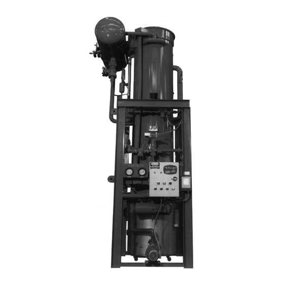
P24AL & P34AL Service Manual INTRODUCTION Special Precautions to Be Observed When Charging Refrigeration Systems. Only technically- qualified persons, experienced and knowledgeable in the handling of anhydrous ammonia refrigerant and operation of refrigeration systems, should perform the operations described in this manual. All local, federal, and EPA regulations must be strictly adhered to when handling ammonia (R-717) refrigerant. - Page 14 P24AL & P34AL Service Manual INTRODUCTION Figure 1-1 P24AL 1” Front Side (Control Panel) 12/2016...
- Page 15 P24AL & P34AL Service Manual INTRODUCTION Figure 1-2 P24AL Right Side 12/2016...
- Page 16 P24AL & P34AL Service Manual INTRODUCTION Figure 1-3 P24AL Back Side 12/2016...
- Page 17 P24AL & P34AL Service Manual INTRODUCTION Figure 1-4 P24AL Left Side 12/2016...
- Page 18 P24AL & P34AL Service Manual INTRODUCTION Figure 1-5 P34AL Front Side (Control Panel) 12/2016...
- Page 19 P24AL & P34AL Service Manual INTRODUCTION Figure 1-6 P34AL Right Side 12/2016...
- Page 20 P24AL & P34AL Service Manual 1-10 INTRODUCTION Figure 1-7 P34AL Back Side 12/2016...
- Page 21 P24AL & P34AL Service Manual 1-11 INTRODUCTION Figure 1-8 P34AL Left Side 12/2016...
- Page 22 P24AL & P34AL Service Manual 1-12 INTRODUCTION 12/2016...
-
Page 23: Receipt Of Your Tube-Ice Machine
Any repair work or alteration to the machine without the permission of the Vogt Ice, LLC can void the machine’s warranty. You should also notify your Vogt distributor or the factory. -
Page 24: Model Designation For P-Series Ice Machine, Figure 2-1
P24AL & P34AL Service Manual RECEIPT OF YOUR TUBE-ICE MACHINE 50T A L A B 5 46 NC 000 Product Variation Code Nominal Capacity A number or letter designator (“T” = tons/day) assigned to specific variations “25T” – 25 tons/day within a family series “50T”... -
Page 25: Installing Your Tube-Ice Machine
® These figures are intended as a guide to unloading and lifting the P24AL and P34AL Tube-Ice machine. Vogt Ice, LLC is not responsible for product damage or personnel injury or loss of life during the loading or lifting process. - Page 26 P24AL & P34AL Service Manual INSTALLING YOUR TUBE-ICE MACHINE Figure 3-1A P24AL Space Diagram (Front View) 12/2016...
- Page 27 P24AL & P34AL Service Manual INSTALLING YOUR TUBE-ICE MACHINE Figure 3-1B P24AL Space Diagram (Side View) 12/2016...
-
Page 28: P24Al Foundation Layout, Figure 3-2
P24AL & P34AL Service Manual INSTALLING YOUR TUBE-ICE MACHINE Figure 3-2 P24AL Foundation Layout 12/2016... - Page 29 P24AL & P34AL Service Manual INSTALLING YOUR TUBE-ICE MACHINE Figure 3-3A P34AL Space Diagram (Front View) 12/2016...
- Page 30 P24AL & P34AL Service Manual INSTALLING YOUR TUBE-ICE MACHINE Figure 3-3B P34AL Space Diagram (Side View) 12/2016...
-
Page 31: P34Al Foundation Layout, Figure 3-4
P24AL & P34AL Service Manual INSTALLING YOUR TUBE-ICE MACHINE Figure 3-4 P34AL Foundation Layout 12/2016... -
Page 32: Lifting Procedure For P24Al, Figure 3-5
P24AL & P34AL Service Manual INSTALLING YOUR TUBE-ICE MACHINE Figure 3-5 Lifting Procedure for P24AL 12/2016... -
Page 33: Lifting Procedure For P34Al, Figure 3-6
P24AL & P34AL Service Manual INSTALLING YOUR TUBE-ICE MACHINE Figure 3-6 Lifting Procedure for P34AL 12/2016... - Page 34 P24AL & P34AL Service Manual 3-10 INSTALLING YOUR TUBE-ICE MACHINE Figure 3-7 Seismic Anchoring Detail for P24AL and P34AL Tube-Ice Machines 12/2016...
-
Page 35: Water Supply, Drain And Refrigeration Connections, Table 3-1
Piping and Drain Connections. See Figures 1-1 to 1-8 and 3-11 to 3-17 for connection locations. When connecting refrigeration piping, you must follow and adhere to all piping codes required in the jurisdiction of installation. Vogt recommends ASHRAE 15 “Safety Standard for Refrigeration Systems,” and ASME B31.5 “Refrigeration Piping and Heat Transfer Components,” which are required in many locations throughout the world. -
Page 36: Water Tank Drain
P24AL & P34AL Service Manual 3-12 INSTALLING YOUR TUBE-ICE MACHINE Water Tank Drain. This valve and connection is for the purpose of flushing and draining the water tank of impurities, foreign material and cleaning chemicals used during servicing. It should be piped to an open drain or sump for visible discharge. - Page 37 P24AL & P34AL Service Manual 3-13 INSTALLING YOUR TUBE-ICE MACHINE cycle is 50%. If the compressor cannot be unloaded, then a hot gas bypass to the suction line must be installed. See Figures 3-13 through 3-16. Cooling Tower (optional). When selecting a cooling tower, careful attention must be given to operating wet bulb conditions.
-
Page 38: Cooling Tower (Optional)
P24AL & P34AL Service Manual 3-14 INSTALLING YOUR TUBE-ICE MACHINE If the condenser inlet water temperature is expected to be below 75F / 24C, a water regulating valve should be installed in the condenser water inlet line and adjusted to maintain a head pressure of not less than 175 psig. -
Page 39: Safety Valves
P24AL & P34AL Service Manual 3-15 INSTALLING YOUR TUBE-ICE MACHINE Figure 3-9 1 Pump / 3-Way Valve * Better Freeze Protection COOLING TOWER WATER COOLED CONDENSER CHECK VALVE INDOOR SUMP Outdoor pump is off until indoor sump needs cooling Figure 3-10 2 Pump / 2-Way Valve * Best Freeze Protection ... -
Page 40: Power Supply Connections, Figure 3-11
P24AL & P34AL Service Manual 3-16 INSTALLING YOUR TUBE-ICE MACHINE Rotation Check). If one leg of the 3 phase power is higher or lower (“wild”), then it should be connected to terminal L3. Connect the ground wire to the “ground” terminal provided. Make sure wires #22 and #27 are connected to the elapse time (ET) indicator in the control panel. -
Page 41: Current Unbalance
P24AL & P34AL Service Manual 3-17 INSTALLING YOUR TUBE-ICE MACHINE Important: If the supply voltage phase unbalance is more the 2%, contact your local electric utility company. Current Unbalance. Voltage unbalance will cause a current unbalance, but a current unbalance does not necessarily mean that a voltage unbalance exists. -
Page 42: Auxiliary Controls Or Equipment
P24AL & P34AL Service Manual 3-18 INSTALLING YOUR TUBE-ICE MACHINE CAUTION Do not attempt to start the machine until first making sure all conditions listed in the Installation Review Checklist and all necessary valves have been opened for operation. CAUTION Auxiliary Controls or Equipment. - Page 43 P24AL & P34AL Service Manual 3-19 INSTALLING YOUR TUBE-ICE MACHINE Figure 3-12 Interconnecting Piping for Vogt P24AL and Vogt 24AHS 12/2016...
-
Page 44: Interconnecting Piping For Vogt P24Al And Dedicated High Side, Figure 3-13
P24AL & P34AL Service Manual 3-20 INSTALLING YOUR TUBE-ICE MACHINE Figure 3-13 Interconnecting Piping for Vogt P24AL and Dedicated High Side 12/2016... -
Page 45: Interconnecting Piping For Vogt P34Al And Dedicated High Side, Figure 3-14
P24AL & P34AL Service Manual 3-21 INSTALLING YOUR TUBE-ICE MACHINE Figure 3-14 Interconnecting Piping for Vogt P34AL and Dedicated High Side 12/2016... -
Page 46: Interconnecting Piping For Vogt P24Al And Central High Side, Figure 3-15
P24AL & P34AL Service Manual 3-22 INSTALLING YOUR TUBE-ICE MACHINE Figure 3-15 Interconnecting Piping for Vogt P24AL and Central High Side 12/2016... -
Page 47: Interconnecting Piping For Vogt P34Al And Central High Side, Figure 3-16
P24AL & P34AL Service Manual 3-23 INSTALLING YOUR TUBE-ICE MACHINE Figure 3-16 Interconnecting Piping for Vogt P34AL and Central High Side 12/2016... - Page 48 P24AL & P34AL Service Manual 3-24 INSTALLING YOUR TUBE-ICE MACHINE Figure 3-17 Interconnecting Piping for 2-Vogt P34AL and Central High Side 12/2016...
- Page 49 P24AL & P34AL Service Manual 3-25 INSTALLING YOUR TUBE-ICE MACHINE Figure 3-18 Interconnecting Piping for 3-Vogt P34AL and Central High Side 12/2016...
-
Page 50: Installation Review: A Checklist
P24AL & P34AL Service Manual 3-26 INSTALLING YOUR TUBE-ICE MACHINE IMPORTANT Be sure to follow the wiring schematic when incorporating overloads of conveyor (5 MOL). Also remove jumpers as instructed. This is necessary to provide proper protection for the Tube-Ice machine and its component parts. -
Page 51: How Your Tube-Ice Machine Works
P24AL & P34AL Service Manual HOW YOUR TUBE-ICE MACHINE WORKS 4. How Your Tube-Ice Machine Works Operating Features. Your low side Tube-Ice machine is an efficient ice producing plant. If installed and maintained properly, it will give many years of operation with a minimum amount of repairs. -
Page 52: Harvest Period
P24AL & P34AL Service Manual HOW YOUR TUBE-ICE MACHINE WORKS “A” liquid feed solenoid valve (20), de-energizes the suction regulator (when installed) and turns out the two pilot lights, LIQUID FEED and FREEZING. Harvest Period. About 20-30 seconds after the 1CR relay is energized, the thaw gas valve (18) opens, the “H”... -
Page 53: Piping Schematic For P24Al, Figure 4-1
P24AL & P34AL Service Manual HOW YOUR TUBE-ICE MACHINE WORKS Figure 4-1 Piping Schematic for P24AL 12/2016... -
Page 54: Piping Schematic For P34Al, Figure 4-2
P24AL & P34AL Service Manual HOW YOUR TUBE-ICE MACHINE WORKS Figure 4-2 Piping Schematic for P34AL 12/2016... -
Page 55: Start-Up And Operation
P24AL & P34AL Service Manual START-UP & OPERATION 5. Start-Up & Operation Refrigeration System Review. The refrigeration system uses anhydrous ammonia (R-717) refrigerant. Following the piping schematic (Figures 3-12 to 3-16 and 4-1 or 4-2), you will see that during the machine’s freeze cycle, the compressor discharge gas goes through the oil separator to remove any oil present in the discharge gas and return the oil to the compressor crankcase. -
Page 56: Start-Up Checklist
P24AL & P34AL Service Manual START-UP & OPERATION Start-up Checklist. Be sure to complete and return the “Warranty Registration/Start-up Report” located in the front of the manual. 1. See that the water-inlet connections are attached properly. The water inlet shutoff valve (62) for the water tank should be open. -
Page 57: Charging From Tank Truck (For Dedicated High Side Only)
P24AL & P34AL Service Manual START-UP & OPERATION Charging from Tank Truck (dedicated high side only). The system may be charged by bulk from a tank truck and be pumped directly into the receiver through the drain valve. Follow these instructions with caution: 1. - Page 58 P24AL & P34AL Service Manual START-UP & OPERATION 9. Set the HAND/AUTO switch (1SS) to the HAND position allowing the circulating water pump to circulate water through the freezer. 10. As the pressure continues to rise in the freezer, start the compressor and pump the ammonia into the receiver.
-
Page 59: Control Panel, Figure 5-1
P24AL & P34AL Service Manual START-UP & OPERATION When charging is complete, stop the machine, disconnect and lockout the power. If the machine contains a pressure switch (2PS), open the control panel door and reconnect wire #24 to the freezer pressure switch. -
Page 60: Start-Up
IMPORTANT Complete the remaining part of the “Warranty/Registration Start-Up Report” and return it to Vogt Ice, LLC. IMPORTANT Check the refrigerant level at the receiver liquid gage glass to make sure it is near the operating level mark. -
Page 61: Operating Tips
P24AL & P34AL Service Manual START-UP & OPERATION 4. Close the cylinder valve immediately when the ammonia feed light comes on and reopen it when the light goes out. Repeat until properly charged. CAUTION Do not leave a refrigerant cylinder attached to the machine unattended. Disconnect it immediately when the machine is charged or the cylinder is empty. - Page 62 P24AL & P34AL Service Manual START-UP & OPERATION 12/2016...
-
Page 63: Bin Level Control
P24AL & P34AL Service Manual ELECTRICAL CONTROLS 6. Electrical Controls Your low side Tube-Ice machine is equipped with a dry contact (3CR) for a compressor motor starter and a transformer (if required) for the control circuit power. The control panel and transformer are mounted on the machine front side (see Figures 1-1 or 1-8). -
Page 64: Control Panel (Door Opened), Figure 6-1
P24AL & P34AL Service Manual ELECTRICAL CONTROLS Figure 6-1 Control Panel (Door Opened) (3CR) Compressor Motor Holding relay for safety and bin level control. Auxiliary contact Starter contact and provides control power to the compressor motor starter. holding relay Continuously energized during freezing and thawing. (2M) Pump Motor Starter Provides power to the circulating water pump during the freezer... -
Page 65: Description Of Control Panel Parts (Outer Door), Table 6-2
P24AL & P34AL Service Manual ELECTRICAL CONTROLS Figure 6-2 Control Panel (Hinged Door) Amber Pilot Light – (1LT) Illuminated during the freeze period or whenever the FREEZING circulating water pump is running. Clear Pilot Light – LIQUID (2LT) Illuminated when the circulating water pump is running and FEED the float switch (10) is closed. - Page 66 P24AL & P34AL Service Manual ELECTRICAL CONTROLS Figure 6-3 Electrical Schematic for P24AL and P34AL all Voltages, 50-60 Hz. 12/2016...
-
Page 67: Maintenance
P24AL & P34AL Service Manual MAINTENANCE 7. Maintenance Preventative Maintenance. A careful inspection of your Tube-Ice machine for leaks and correct operational functions at the time of installation and start-up will begin a long, satisfactory life of service. In order to insure this degree of dependability, a systematic maintenance program is necessary. -
Page 68: Preventative Maintenance Form
P24AL & P34AL Service Manual MAINTENANCE PREVENTATIVE MAINTENANCE FORM This form can be removed and duplicated for record keeping. Date: _____________ Model #: ________________________ Serial #: _____________ The following service performed and checked: Hour meter reading _______________, Ambient temperature (inside)_______ F Make-Up water float valve adjusted properly Water distributors clean and in place All drains freely draining... -
Page 69: Ice-Making Section
P24AL & P34AL Service Manual MAINTENANCE Ice Making Section. The ice making section of the Tube-Ice machine should be cleaned at least twice a year (more often if water conditions cause mineral build-up). Use an approved food-grade ice machine cleaner. The water pump is used to circulate the cleaner through the system. For complete instructions, follow the “Cleaning Procedure”... -
Page 70: Water Distributors, Table 7-1
P24AL & P34AL Service Manual MAINTENANCE 1 1/2” 1 1/4” 1” Tube Size Model Number of Distributors P24A P34A Table 7-1 Water Distributors You may look through the plastic freezer cover to inspect the water distributors if the view is clear. For a closer inspection you should stop the unit, remove the nuts and retaining ring sections and lift off the top cover. - Page 71 P24AL & P34AL Service Manual MAINTENANCE To clean the water tank: 1. Stop the machine at the end of harvest. 2. Shut off the make-up water supply. 3. Open the drain valve and drain the tank. 4. Remove the water box cover and flush out any loose sediment from the tank. The wire mesh screen can be removed if necessary.
-
Page 72: Compressor (Optional)
P24AL & P34AL Service Manual MAINTENANCE Frequency Thereafter Change oil 200 hr. 500 hr. 1500 hr. 4000 hr. every 4000 hrs. Clean suction strainer cloth 200 hr. 500 hr. Remove if clogging is minimal Table 7-4 Compressor Maintenance The above maintenance is only a guide. The compressor should be inspected anytime there is unusual noise, damage is suspected or the oil becomes discolored. -
Page 73: Troubleshooting
P24AL & P34AL Service Manual TROUBLESHOOTING 8. Troubleshooting Note: Your machine’s electrical system has several built-in safety and overload protection features to stop operation when a single component fails or if there is a problem from an outside source such a power supply. Make sure all auxiliary equipment is connected to incorporate safety and overload circuits and protect all related equipment. - Page 74 P24A & P34A Service Manual TROUBLESHOOTING Symptom: Machine Stopped Possible Cause Possible Remedy Power failure or interruption Check fused disconnect or circuit breaker supplying power to the machine. If power has been off, make sure the crankcase heater is energized and there is no liquid refrigerant in the compressor crankcase prior to restarting the compressor.
- Page 75 P24AL & P34AL Service Manual TROUBLESHOOTING Symptom: Machine Stopped (con’t) Possible Cause Possible Remedy High/Low pressure safety switch (1PS or 4PS) If the machine stops by low pressure cutout, the tripped (optional) switch will reset automatically when the pressure raises to the “cut-in” setting. Check thaw gas valve (18) to make sure it opens during harvest time.
- Page 76 P24A & P34A Service Manual TROUBLESHOOTING Symptom: Freeze-up due to extended freeze period Possible Cause Possible Remedy Freeze timer (1TR) set to long Adjust timer or replace if defective. See Figure 9-2. Freezer pressure switch (2PS) set too low or Adjust switch or replace if defective.
- Page 77 P24AL & P34AL Service Manual TROUBLESHOOTING Symptom: Freeze-up due to ice failing to discharge Possible Cause Possible Remedy Freeze timer (1TR) set to long Adjust timer or replace if defective. See Figure 9-2. Extended freeze period (if 2PS is used) Check freezer pressure...
-
Page 78: Hand Expansion Valve
P24A & P34A Service Manual TROUBLESHOOTING Symptom: Low ice capacity. Suspicions of low ice capacity should be confirmed by accurate calculations of actual ice product. Much weight can be lost by melting and off fall through augers and other ice handling equipment. 1. - Page 79 P24AL & P34AL Service Manual TROUBLESHOOTING Symptom: Low ice capacity (cont.) Possible Cause Possible Remedy Excessively high head pressure Check cooling tower or evaporative condenser to make sure sufficient water is provided for cooling and the equipment is operational to cool the water.
- Page 80 P24A & P34A Service Manual TROUBLESHOOTING Symptom: High discharge pressure (check gage accuracy) Possible Cause Possible Remedy Insufficient water flow through the cooling Check the condenser water pump to make sure tower or condenser it is pumping enough water as specified in Page 3-13.
- Page 81 P24AL & P34AL Service Manual TROUBLESHOOTING Symptom: Low discharge pressure (check gage accuracy) Possible Cause Possible Remedy Fan cycling switch out of adjustment or Check adjustment. Replace if defective. defective Compressor running unloaded or not pumping Check compressor motor amp. If the efficiently compressor is running unloaded, the amperage...
- Page 82 P24A & P34A Service Manual 8-10 TROUBLESHOOTING Symptom: Compressor oil pressure low (check gages) See Section 7, for compressor oil pressure requirements. Possible Cause Possible Remedy Oil diluted with refrigerant Oil will be very foamy. Check liquid feed control for overfeed problem. Oil pressure regulating valve out of adjustment Adjust valve to increase oil pressure.
- Page 83 P24AL & P34AL Service Manual 8-11 TROUBLESHOOTING Symptom: Machine short cycles (using freeze pressure switch (2PS) only) Possible Cause Possible Remedy Freezer pressure switch (2PS) set too low or Adjust switch or replace if defective. defective Figure 9-3. See “Freeze-up due to extended freezer period” Freeze-up and “Freeze-up due to ice failing to discharge”.
- Page 84 P24A & P34A Service Manual 8-12 TROUBLESHOOTING 12/2016...
-
Page 85: Automatic Blow Down (Harvest Cycle)
P24AL & P34AL Service Manual SERVICING OPERATIONS 9. Servicing Operations Automatic Blowdown (harvest cycle). A feature of this machine is a solenoid activated flushing valve (63) which is provided to eliminate or reduce the necessity for frequent flushing or cleaning of the water tank. -
Page 86: Freeze Timer
P24AL & P34AL Service Manual SERVICING OPERATIONS Figure 9-1 P24AL and P34AL Float Height Hand Expansion Valve. The hand expansion valve is located directly after the “A1” solenoid valve. This valve should be set at a point where the float switch is open for a length of time approximately equal to the time that it is closed. -
Page 87: Miniature Rocker Switch Settings For Freeze Timer, Table 9-1
P24AL & P34AL Service Manual SERVICING OPERATIONS Switch Table 9-1 Miniature Rocker Switch Settings for Freeze Timer Entering and Displaying Set Points. Whenever the freeze timer unit is powered up and the previous setpoint has been lost, the digit display indicates four hyphens. The unit will not operate until it has been provided with a setpoint, clearing the display of hyphens. -
Page 88: Freeze Timer, Figure 9-2
P24AL & P34AL Service Manual SERVICING OPERATIONS Figure 9-2 Freeze Timer (1TR) Freezer Pressure Switch (optional). The freezing time period for producing ice of a desired thickness is controlled by the freezer pressure switch (2PS), Figure 9-3, located inside the control panel. -
Page 89: Control Circuit Protection
P24AL & P34AL Service Manual SERVICING OPERATIONS Figure 9-3 ASCO Freezer Pressure Switch (2PS) It is preferable that the freezing cycle be such that a small diameter hole remains in the center of the ice cylinder (1/16” diameter for 7/8” diameter ice, 1/8” diameter for 1 1/8” diameter ice, 1/4” diameter for 1 3/8”... -
Page 90: Thawing Timer
The cleaning tools should be rotated at the specified speed for the particular tool used. The tubes should be kept wet during cleaning. After cleaning the tubes should be flushed thoroughly and all foreign material removed. Contact your distributor or Vogt’s Service Department to obtain the proper cleaning tools. -
Page 91: Cutter Gear Reducer
P24AL & P34AL Service Manual SERVICING OPERATIONS Cutter Gear Reducer. The cutter motor and gear reducer (54), Figure 9-5A, drive the ring gear of the cutter assembly. It is important that the teeth of the drive gear and the ring gear mesh properly both vertically and horizontally. -
Page 92: Gear Reducer Replacement
P24AL & P34AL Service Manual SERVICING OPERATIONS Gear Reducer Replacement. 1. Disconnect and lock out all power to the machine. 2. Disconnect electrical wires and conduit from the motor. 3. Remove the top and side bolts holding the mounting plate to the support bracket and lift the plate and gear reducer assembly from the tank bracket. -
Page 93: Water Tank And Cutter Parts Weights, Table 9-2
P24AL & P34AL Service Manual SERVICING OPERATIONS Weight (lbs.) Description Water tank (bare) Bearing bracket assembly and cutter disc Cutter assembly and ring gear Water tank and cutter assembly Cutter disc Cutter drive gear Gear reducer and motor Water pump Table 9-2 Water Tank and Cutter Parts Weights Water Tank Removal... -
Page 94: Bearing Bracket And Cutter Disc Removal
P24AL & P34AL Service Manual 9-10 SERVICING OPERATIONS 5. Rotate the cutter, aligning the shaft and hub key way and inserting the key to its full depth. 6. Install the gasket, the retainer, and the socket head cap screw and tighten to approximately 15 ft. lb. -
Page 95: Cutter Height Adjustment
P24AL & P34AL Service Manual 9-11 SERVICING OPERATIONS 5. Slide the upper bearing spacer on the shaft and begin driving the shaft down through the middle bearing of the housing. Do not start the top shaft bearing in the housing. 6. -
Page 96: Water Tank Installation
P24AL & P34AL Service Manual 9-12 SERVICING OPERATIONS Water Tank Installation. 1. Place the 3/16” thick gum rubber gasket on the top of the tank flange. It can be held in place with narrow strips of tape through the bolt holes. 2. -
Page 97: P24A Water Tank Assembly, Figure 9-5B
P24AL & P34AL Service Manual 9-13 SERVICING OPERATIONS Figure 9-5B P24A Water Tank Assembly 12/2016... - Page 98 P24AL & P34AL Service Manual 9-14 SERVICING OPERATIONS Item # Description P24A Part Number P34A Part Number Water Tank Assembly 19T4500S2400 19T4500S3400 Water Box Cover (Not Shown) 19T2150C0100 19T2150C0200 Water Pump See Pump Model # See Pump Model # 5/8”-11 NC x 3” Long S.S. Stud 12A 2222L11190000 12A 2222L11190000 5/8”-11 NC x 2”...
-
Page 99: Cutter Ring Gear Replacement
P24AL & P34AL Service Manual 9-15 SERVICING OPERATIONS Item # Description P24A Part Number P34A Part Number Splash Curtain Holder 19T4001S0162 19T4001S0163 Splash Curtain Bottom Plate 19T4001S0415 19T4001S0411 Splash Curtain 12A 4078C03000000 12A 4078C02000000 Cutter Ring Gear Replacement. 1. Remove the water tank assembly (see water tank removal). 2. -
Page 100: Cutter Blade And Adapter Plate Adjustment, Figure 9-6
P24AL & P34AL Service Manual 9-16 SERVICING OPERATIONS Figure 9-6 Cutter Blade and Adapter Plate Adjustment Cutter Adapter Plate Installation. 1. Disconnect and lock-out all power to the machine and remove the water tank assembly so the cutter is accessible (see water tank removal). 2. -
Page 101: Removal Of Ammonia Refrigerant From The Machine
P24AL & P34AL Service Manual 9-17 SERVICING OPERATIONS To perform a pumpdown, follow this procedure: 1. With the machine running, close the liquid feed stop valve nearest the receiver. 2. Open the water tank drain valve partially to allow a continuous flow of warm make-up water into the water tank and still maintain a good level in the tank. -
Page 102: Purging Non-Condensables
P24AL & P34AL Service Manual 9-18 SERVICING OPERATIONS Apply soap solutions with a narrow brush or spray bottle to all joints, welds, or areas of suspicion. The solution will form bubbles if there is a leak. Sulfur sticks and test paper can be obtained from your ammonia supplier. ... -
Page 103: Draining The Oil Trap
P24AL & P34AL Service Manual 9-19 SERVICING OPERATIONS Follow this procedure when purging: 1. Connect a suitable hose to the purge valve and place the other end in water. 2. Open (slightly) the purge valve and allow air to escape. 3. -
Page 104: Circulating Water Pump Motor
P24AL & P34AL Service Manual 9-20 SERVICING OPERATIONS 7. Close the compressor discharge stop valve and the oil return valve. Make sure the power is disconnected and locked-out. 8. Drain the compressor oil, remove the compressor side cover and clean the inside of all oil and foreign matter, and reinstall the side cover. -
Page 105: Thaw Gas Solenoid Valve, Figure 9-7
P24AL & P34AL Service Manual 9-21 SERVICING OPERATIONS 5. With the valve manually opened (stem out), open slightly only one stop valve (90) and purge air from the line through the 1/4” tubing compression nut at the strainer. Then close that valve (90) and open the other valve (90) to purge air from that section of the line. - Page 106 P24AL & P34AL Service Manual 9-22 SERVICING OPERATIONS Repair or replace as follows: 1. With the receiver pressure higher than the freezer pressure close the hand stop valve (58) and (29) (upstream and downstream) in the liquid line between the receiver and liquid feed solenoid valve.
-
Page 107: Water Flush Solenoid Valve
P24AL & P34AL Service Manual 9-23 SERVICING OPERATIONS Figure 9-9 Thaw Gas Check Valve Water Flush Solenoid Valve (63) is opened during the thaw (harvest) cycle, to flush out some of the impurities form the water in the tank, thereby improving the ice quality. Repair or replace as follows: 1. -
Page 108: Belt Tension
P24AL & P34AL Service Manual 9-24 SERVICING OPERATIONS 3. Drain the oil through the oil drain valve located at the base of the compressor and purge the compressor until all pressure is relieved. 4. Remove the compressor side cover (hand-hole cover) being careful to protect the gasket and surface from damage. -
Page 109: Compressor Servicing
P24AL & P34AL Service Manual 9-25 SERVICING OPERATIONS 6. Check the motor and compressor shafts to make sure they are parallel, and check the flywheel and motor sheave with a straight edge, string, or wire to make sure they are parallel and in the same plain. - Page 110 P24AL & P34AL Service Manual 9-26 SERVICING OPERATIONS 12/2016...
-
Page 111: 10. Options And Accessories
P24AL & P34AL Service Manual 10-1 OPTIONS AND ACCESSORIES 10. Options and Accessories Crushed Ice Production. Your P24 or P34 Tube-Ice machine is capable of producing crushed ice with no loss of capacity; however, there are certain changes to be made in order to convert to crushed ice production. -
Page 112: Mitsubishi E1012 Operator Interface, Figure 10-1
P24AL & P34AL Service Manual 10-2 OPTIONS AND ACCESSORIES The PLC/Interface adds features such as selectable “Automatic Restart” after a power failure, choice of timed or pressure switch controlled freeze cycles and Freezer “Pumpdown”. For package units, the machine will automatically “Pumpdown” before cycling off. The PLC/Interface provides the following programmable functions: ... -
Page 113: Mitsubishi Plc
P24AL & P34AL Service Manual 10-3 OPTIONS AND ACCESSORIES The Mitsubishi unit also records the last 10 machine cycles. This data can be viewed by pressing the HISTORY button on the interface until the CYCLE HISTORY title appears. Press the down arrow to scroll through the information. -
Page 114: Mitsubishi Plc Input / Outputs, Table 10-1
P24AL & P34AL Service Manual 10-4 OPTIONS AND ACCESSORIES Figure 10-3 Mitsubishi FX3GE-24MR PLC and FX -8ER-ES/UL (Used after 2015) Inputs Description Outputs Description Not used Not used Not used High Side Control Interlock Start / Manual Harvest Button Conveyor Control Contact Selector Switch (Clean position) ET - Elapsed Timer Selector Switch (Ice position) -
Page 115: Wiring Schematic - P24Al/P34Al With Mitsubishi Plc, Figure 10-4
P24AL & P34AL Service Manual 10-5 OPTIONS AND ACCESSORIES Figure 10-4 Wiring Schematic – P24AL/P34AL with Mitsubishi PLC 12/2016... -
Page 116: Power Monitor
10-6 OPTIONS AND ACCESSORIES Power Monitor, Wagner Model # DTP-3. All Vogt Tube-Ice machine models are available from the factory with a three phase line voltage power monitor with LCD display. The units are also available for after market or retrofit installation. These units monitor line voltage inputs from 190 to 610 volts and provide protection against line voltage variances which can damage or destroy the compressor motor. -
Page 117: Power Monitor Parameter Limits, Table 10-2
P24AL & P34AL Service Manual 10-7 OPTIONS AND ACCESSORIES Parameter Minimum Maximum Default Recommended Unit Settings Line Side Voltage (Nominal Supply voltage Volts Voltage) Under /Over Voltage (tolerance) Phase Unbalance Lockout Time (Delay on Break) Seconds Delay Time (Delay on Make) Seconds Response Time (Delay on Fault) Seconds... - Page 118 P24AL & P34AL Service Manual 10-8 OPTIONS AND ACCESSORIES Display of fault memories (MEM flashes). Pressing up or down displays the last fault conditions that took the unit off line. The first 25 faults are recorded. The top number displayed represents the fault memory.
- Page 119 (4) Compressor Requirements is based on 16F suction temperature, 100°F condensing temperature, 70°F ambient, and 25% blow down. (5) Makeup water is maximum value and includes 25% blow down each cycle. Vogt reserves the right to change designs and specifications without notice. Table 11-1...
- Page 120 (4) Compressor Requirements is based on 16F suction temperature, 100°F condensing temperature, 70°F ambient, and 25% blow down. (5) Makeup water is maximum value and includes 25% blow down each cycle. Vogt reserves the right to change designs and specifications without notice. Table 11-2...
- Page 121 P24AL & P34AL Service Manual 11-3 TABLES & CHARTS Cylinder Ice Crushed Ice Make-Up Water Tube Size Tube Size 1” 1 1/4” 1 1/2” 1” 1 1/4” 1 1/2” Temp. °F 5.25 5.59 5.18 6.30 6.98 6.47 4.96 5.26 4.88 6.20 6.57 4.71...
- Page 122 P24AL & P34AL Service Manual 11-4 TABLES & CHARTS Suction Pressure Discharge Pressure Harvest Times Ice per Freeze Time (psig) (psig) (secs) Cycle (minutes) End of End of End of End of First All Ice Total Water Temperature (deg. F) Average Freeze Thaw...
-
Page 123: Recommended Spare Parts List
P24AL & P34AL Service Manual 11-5 TABLES & CHARTS RECOMMENDED SPARE PARTS LIST ® Vogt Model P24AL and P34AL Tube-Ice Machine P24A PART NO. P34A PART NO. DESCRIPTION 12A-7503E22000000 12A-7503E22000000 Thaw timer 208/230 Suction pressure gage 30”-150# 12A-2590G12000000 12A-2590G12000000 Discharge pressure gage 30”-300#... - Page 124 P24AL & P34AL Service Manual 11-6 TABLES & CHARTS TEMPERATURE - PRESSURE CHART FOR COMMON REFRIGERANTS (°F-psig) DegF R-12 R-22 R-502 R-134a R-404A R-717 MP-39 DegF R-12 R-22 R-502 R-134a R-404A R-717 MP-39 -7.6 -3.0 -9.0 -7.0 -9.1 46.7 84.0 97.4 45.5 102.9...
-
Page 125: Conversion Factors: English To Metric, Table 11-8
P24AL & P34AL Service Manual 11-7 TABLES & CHARTS REFERENCE INFORMATION CONVERSION FACTORS: English to Metric To Convert From Multiply by Area 9.2903e-2 6.416 e-4 Energy Joule (J) 1054.48 BTU/Hr 2546.2 1.34 Length 0.3048 0.0254 Pressure lbf/ft Paschals 47.88 lbf/in (psi) Paschals 6894.76... - Page 126 P24AL & P34AL Service Manual 11-8 TABLES & CHARTS 12/16/16...
- Page 127 P24AL & P34AL Service Manual 12-1 INDEX 12. Index Cutter Gear Reducer ---------------------------------------------- 7-7, 9-7 A Brief History of Henry Vogt Machine Co. ---------------------- 1-1 drive gear replacement ----------------------------------------- 9-7 Adding Refrigerant------------------------------------------------------5-6 gear reducer replacement -------------------------------------- 9-8 Ammonia Specification by Grade ------------------------------------5-2...
- Page 128 12-2 P24AL & P34AL Service Manual INDEX Operating Vitals (P24AL and P34AL) ----------------------------- 11-5 Ice Lb./Kg Harvest ------------------------------------------------------2-2 Operating Weight------------------------------------------------------- 2-3 Ice-Making Section (Cleaning Procedure) --------------------------7-3 Ice Quality ----------------------------------------------------------------8-7 Important Safety Notice ------------------------------------------------1-2 P24AL ----------------------------------------------------------------------- Initial Torque Adjustment (Soft Starter) ------------------------- 10-13 heat rejection --------------------------------------------------- 3-13 Inspection, First Arrival ------------------------------------------------2-1 make-up water usage ------------------------------------------ 11-4...
- Page 129 P24AL & P34ALService Manual 12-3 INDEX R - 717 (Refrigerant) ---------------------------------------------------5-1 Rated Capacity ----------------------------------------------------------2-3 Receipt of Machine -----------------------------------------------------2-1 inspection ---------------------------------------------------------2-1 Valves ------------------------------------------------------------------- 9-20 description ---------------------------------------------------------2-1 Valves (location) ------------------------- see figures 1-1 through 1-12 safety tags and labels --------------------------------------------2-2 Voltage Unbalance --------------------------------------------------- 3-16 Receiver Ammonia Drain Valve (44) ------------------------------ 1-11 Receiver Purge Valve (59) ------------------------------------------- 1-10 Refrigerant, Adding -----------------------------------------------------5-6...
- Page 130 12-4 P24AL & P34AL Service Manual INDEX 12/2016...
- Page 131 Appendix A...
- Page 132 Material Safety Data Sheet # 4001 OCHE NDUSTRIES INC 2/15/96 SECTION 1: CHEMICAL PRODUCT & COMPANY IDENTIFICATION CHEMICAL NAME: Anhydrous Ammonia TRADE NAMES/SYNONYMS Ammonia PRODUCT CODE: 5B81-83 MANUFACTURER AND/OR DISTRIBUTOR: EMERGENCY TELEPHONE NUMBERS: LaRoche Industries Inc. Transportation (CHEMTREC): (800) 424-9300 1100 Johnson Ferry Rd., NE Environmental/Health/Safety: (800) 528-4963...
- Page 133 SECTION 8: EXPOSURE CONTROLS/PERSONAL PROTECTION RESPIRATORY PROTECTION: Respiratory protection approved by NIOSH/MSHA for ammonia must be used when exposure limits are exceeded. Whether a chemical cartridge respirator or a self-contained breathing apparatus is sufficient for effective respiratory protection depends on the type and magnitude of exposure. EYE PROTECTION: Chemical splash goggles, approved for use with ammonia, must be worn to prevent eye contact with liquid or vapor.
- Page 135 Copyright 1989 by LaRoche Industries Inc. All rights reserved. Quotation or production in whole or part without written permission is expressly prohibited.
- Page 149 VOGT® TUBE-ICE® MACHINE BASIC PRODUCT WARRANTY Vogt Tube Ice LLC, hereinafter referred to as SELLER, warrants to the pipework and similar items of obstruction or for any cost brought about by original Purchaser from SELLER or the original end-user, hereinafter the necessity of removing the product from its point of installation.
Need help?
Do you have a question about the P-24AL and is the answer not in the manual?
Questions and answers