
Related Manuals for Hirschmann OZD 485 G12 BAS


Summary of Contents for Hirschmann OZD 485 G12 BAS
- Page 1 Manual Universal RS 485 Fiberoptic Repeater OZD 485 G12 BAS OZD 485 G12 BAS System DA/STAT Port 1 Hirschmann. Simply a good Connection.
- Page 2 All the lia- it describes. However, inconsistencies cannot be ruled bilities of Hirschmann result from the respective sales out, and thus we cannot guarantee absolute consistency. contract, which also contains the complete and solely Nevertheless, the information in the document is chek- valid guarantee regulations.
- Page 3 Notes on safety General safety instructions This manual contains instructions to be observed for This device is operated by electricity. You must follow ensuring your personal safety and for preventing damage. precisely the prescribed safety requirements in the The warnings appear next to a warning triangle with a operating manual that relate to the voltage connect- different heading depending on the degree of danger ions!
- Page 4 EN 55022:1998+A1:2000+A2:2003 Class A Safety instructions for housing Warning! Warning! Only technicians authorized by Hirschmann are This is a Class A device. This equipment may permitted to open the housing. cause radio interference if used in a residential area; in this case it is the operator’s responsibility to take appropriate measures.
- Page 5 FCC RULES Recycling note This device complies with part 15 of the FCC Rules. After usage, this product must be disposed of Operation is subject to the following two conditions: properly as electronic waste in accordance with the current disposal regulations of your county/ (1) This device may not cause harmful interference, and state/country.
- Page 6 Version 1.0 03/06...
-
Page 7: Table Of Contents
Contents Contents 1 Introduction ............. . 2 Half duplex operation . - Page 8 Version 1.0 03/06...
-
Page 9: Introduction
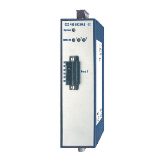
1, electrical Port 1 pull-up/pull-down resistors and characteristic impedance Port 2 Port 3 optical, optical, BFOC/2.5 BFOC/2.5 socket socket Fig. 1: Fiberoptic Repeater OZD 485 G12 BAS with location of individual ports, terminal blocks and LED displays Version 1.0 03/06... - Page 10 – due to the potential separation – on the Repeater itself. Compatibilty with other RS 485 Fiberoptic Repeaters The OZD 485 G12 BAS may be operated via the optical ports in conjunction with the RS 485 Fiberoptic Repea- ters OZD 485 G12 PRO and OZD 485 G12 as long as only those properties that are also supported by the OZD 485 G12 BAS are used in the entire network.
-
Page 11: Half Duplex Operation
G12 BAS. master/slave operation. Access procedures where there You can cascade a number of OZD 485 G12 BAS via the is a risk of collisions, such as CAN, are not permissible. optical interfaces. Devices or bus segments may be connected to the electrical interfaces of all the cascaded OZD 485. - Page 12 2 Half duplex operation Version 1.0 03/06...
-
Page 13: Tristate Recognition Through Permanent High
3 Tristate recognition through permanent highHigh 3 Tristate recognition through permanent high One 2-wire lead, terminated by a characteristic impe- repeaters identify this as tristate and switch their trans- dence and additional pull-up/pull-down resistors, is mitters to the idle state (transmitter set to high-resist- replaced (e.g. - Page 14 3 Tristate recognition through permanent highHigh Version 1.0 03/06...
-
Page 15: Network Topologies
4 Network topologies 4.1 Line topology without redundancy 4 Network topologies 4.1 Line topology without redundancy This network topology can be used for an optical connection of end devices or bus segments. Terminal device(s)/ Terminal device(s)/ Terminal device(s)/ bus segment bus segment bus segment Port 1... -
Page 16: Star Distributor
The star distributor is made by coupling two or more must have the same resistance values as the termination OZD 485 G12 BAS via the electrical interfaces. Lines or of the bus. other star distributors can be connected to the optical The star distributor can be used to create bridges interfaces of the coupled repeaters. -
Page 17: Network Range
Number 8 12 16 20 24 28 32 36 40 44 48 The increase in jitter for each OZD 485 G12 BAS is 10 ns. of devices The result of this is that there may be up to 20 OZD 485 G12 BAS in the transmission link (see fig. - Page 18 4 Network topologies Subkapitel Version 1.0 03/06...
-
Page 19: Installation
Reducing interference by providing adequate space Please note: A simple yet effective way of reducing interference is Between an OZD 485 G12 BAS and a power switching to separate devices and cables causing interference element (e.g. contractor, relay, temperature regulator, from those affected by interference. - Page 20 The power supply wires (+24 VDC and 0 V) for the - Always attach the shields at both ends of the bus OZD 485 G12 BAS must not be laid in the same cable lines. The legal requirements regarding interference duct as cables for load circuits.
-
Page 21: Use In North America
Use 60/75 or 75 °C copper(CU)wire only. For use in Class 2 Circuits. 5.3 Installation procedure The RS 485 Fiberoptic Repeater OZD 485 G12 BAS is Installing repeater installed by the following steps: Installing terminating resistors and (as long as the... -
Page 22: Installing Repeater
5 Installation 5.4 Installing repeater 5.4 Installing repeater The Fiberoptic Repeater OZD 485 G12 BAS can be mounted on a 35 mm DIN rail in accordance with IEC 60715: 1981 + A1: 1995. Install the device in a location where the climatic threshold values specified in the technical data are adhered to. -
Page 23: Installing Terminating Resistor And Pull-Up/Pull-Down Resistors
(see also chap. 3, p. 11). typ. 220 Ω If there is an OZD 485 G12 BAS at the start or end of a Bus line data line, then the terminating resistor and the pull- typ. -
Page 24: Connecting The Electric Bus Cables
5 Installation 5.7 Connecting the electric bus cables 5.7 Connecting the electric bus cables The bus cables are connected by means of the plugable screw terminal block on the front of the device. To connect the cables, loosen the screws on the top line section and remove it. -
Page 25: Connecting The Operating Voltage Supply
5 Installation 5.9 Connecting the operating voltage supply 5.9 Connecting the operating voltage supply Only supply the repeater with a stabilized safety n.c. extra-low voltage (SELV) in accordance with n.c. IEC / EN 60 950/VDE 0805, maximum +32 V (typically +24 V). - Page 26 5 Installation Version 1.0 03/06...
-
Page 27: Bus Configurations
Port 2 Port 3 Fig. 15: Example of connection of OZD 485 G12 BAS to bitbus with twisted pair cable type A (above) or type B (below). The PIN numbers on the ends of the lines refer to the 9-pin sub-D connections prescribed in the standard. -
Page 28: Configuration Of Other Bus Systems
Service Center (for address, see chap. 7.4, p. 29). the bus system has and – derived from this – the type of tristate identification. The OZD 485 G12 BAS only sup- ports RS 485 bus systems that have a high level in the idle phase (for tristate). -
Page 29: Help With Problems
7 Help with problems 7.1 LED displays 7 Help with problems 7.1 LED displays OZD 485 G12 BAS System DA/STAT Fig. 16: LED indicators on the front panel LED display Possible causes System green – Repeater operating correctly – Supply voltage interrupted –... -
Page 30: Troubleshooting
7.4, p. 29): 10. Name and manufacturer of the field bus system? 1. Exact type designation of the OZD 485 G12 BAS. For identification purposes, please provide the order number printed on the device (18 digits). -
Page 31: Contact Address
7 Help with problems 7.4 Contact address 7.4 Contact address Contact address for technical support Hirschmann Automation and Control GmbH Stuttgarter Strasse 45 - 51 72654 Neckartenzlingen Germany/Allemagne Tel.: ++49 / 1805/ 14-1538 Fax: ++49 / 7127/ 14-1551 E-Mail: hac-support@hirschmann.de Internet: http://www.hirschmann.com... - Page 32 7 Help with problems Version 1.0 03/06...
-
Page 33: Technical Data
8 Technical Data 8 Technical Data Repeater OZD 485 G12 BAS Order No. 943 893-321 Voltage/power supply Operating voltage NEC Class 2 power source 18 to 32 VDC (typically 24 VDC) Safety extra-low voltage (SELV/PELV) (redundant inputs decoupled), max. 5 A, buffer time min. 10 ms at 24 VDC... - Page 34 8 Technical Data Repeater OZD 485 G12 BAS Order No. 943 893-321 Climatic ambient conditions Ambient temperature – 25 °C to + 70 °C (IEC 60068-2-1, IEC 60068-2-2) Storage temperature – 25 °C to + 80 °C (IEC 60068-2-14) Relative humidity <...
- Page 36 Hirschmann Automation and Control GmbH Stuttgarter Strasse 45 - 51 72654 Neckartenzlingen Germany/Allemagne Tel.: ++49 / 1805/ 14-1538 Fax: ++49 / 7127/ 14-1551 E-Mail: hac-support@hirschmann.de Internet: http://www.hirschmann.com 039 554-001-E-01-0306 Printed in Germany...
Need help?
Do you have a question about the OZD 485 G12 BAS and is the answer not in the manual?
Questions and answers