Table of Contents
Advertisement
Quick Links
See also:
Manual
Advertisement
Table of Contents

Subscribe to Our Youtube Channel
Related Manuals for Hirschmann OZD FIP G3


Summary of Contents for Hirschmann OZD FIP G3
- Page 1 Description and Operating Instructions Fiber-Optic FIP Repeater OZD FIP G3 OZD FIP G3 System Port 1 Port 2 Port 3 Port 1...
- Page 2 The following Description and Operating Instructions have been produced by Richard Hirschmann GmbH & Co. to the best of the company's knowledge. Hirschmann reserves the right to amend the contents of this description and operating instructions without prior notice.
-
Page 3: Table Of Contents
Contents Contents 1 Introduction ............. 2 Network Topologies . - Page 4 Version 1.0 11/97...
-
Page 5: Introduction
Port 2 Port 3 Optical, Optical, BFOC/2,5 BFOC/2,5 socket socket Fig. 1: Fiber-optic FIP repeater OZD FIP G3. The illustration shows the position of the individual ports, the terminal block, the LED indicators, and the grounding screw. Version 1.0 11/97... -
Page 6: Port
(5 ns/m) and the transfer time through a repeater (< 1µs). The fiber-optic FIP repeater OZD FIP G3 functions At a maximum transmission distance of 2.5 km, the at a transmission rate of 1 MBit/s (as defined in response time is as follows: EN 50 170). -
Page 7: Network Topologies
It is advisable to install the duplex optical cables of optical ring. the two optical channels along different routes. The failure of an optical cable between any two OZD FIP G3 repeaters does not affect the availability of the network. Port 2 Port 3... - Page 8 Fig. 2. long“ fiber-optic line sections. In this case, each repeater is linked (in spatial terms) Port 2 Port 3 Port 2 Port 3 OZD FIP G3 OZD FIP G3 Port 2 Port 3 Port 2 Port 3 OZD FIP G3...
-
Page 9: Line Topology Without Redundancy
Port 2 Port 3 Port 2 Port 3 Port 2 Port 3 Port 2 Port 3 OZD FIP G3 OZD FIP G3 OZD FIP G3 OZD FIP G3 Terminal unit(s)/ Terminal unit(s)/ Terminal unit(s)/ Terminal unit(s)/ bus segment(s) - Page 10 2 Network Topologies Version 1.0 11/97...
-
Page 11: Start-Up
Never connect the fiber-optic FIP repeaters to be used in the manner indicated in this version OZD FIP G3 to 110 V – 240 V mains voltage. of the “Description and Operating Instructions“. Particular attention is to be paid to all warnings The installation location is to be selected so as to and items of information relating to safety. -
Page 12: Connection Of Optical Bus Lines
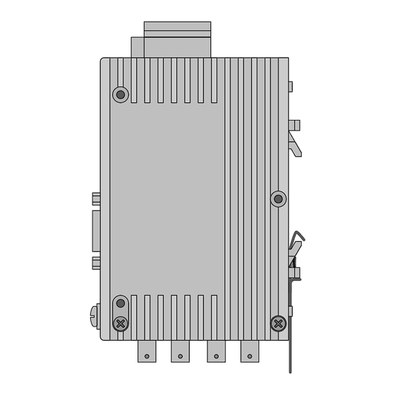
Fig. 5: View of underside of repeater with optical ports 2 and 3 the optical components 3.4 Mounting repeaters The FIP repeater OZD FIP G3 can either be mounted ter must be provided with a low-impedance and on a 35 mm top-hat rail as per EN 50022 or directly on low-inductance ground connection directly via the a flat surface. - Page 13 Mounting on mounting plate The repeater has three through-holes to permit moun- ting to any flat surface, e.g. on the mounting plate of a switch cabinet. 61.2 mm OZD FIP G3 System Port 1 Port 2 Port 3 Ø 3 mm Port 1 Ø...
-
Page 14: Connection Of Electrical Bus Lines
3 Start-Up 3.5 Connection of electrical bus lines 3.5 Connection of electrical bus lines Only bus lines to the French Standard NF-C 46-604 equipment. Max. length 2 m. should be used as the FIP bus line. The electrical port must not be internally termi- The electrical FIP interface (Port 1) is a 9-pole nated. -
Page 15: Connection Of Signaling Contact Lines
Limit values of relay contact signaling contact at the 5-pole terminal block. – Max. switching voltage 60 V DC; 42 V AC If the OZD FIP G3 is functioning correctly, the relay – Max. switching current: 1.0 A picks up and the contact closes. -
Page 16: Esd Protection
3 Start-Up 3.8 ESD protection 3.8 ESD protection When the voltage supply and signaling contact Ensure that the insulation of the connection lines lines have been connected, the access points to the reaches the interior of the terminal block. connection screws of the terminal block must be sealed using the supplied protective plugs. -
Page 17: Led Indicators
4 LED Indicators 4 LED Indicators System Green: Repeater in operation, data traffic occurring OZD FIP G3 Red: – No data received at Port 2 and/or Port 3 (e.g. cable breakage) System – No data traffic at any port for over 500 ms... -
Page 18: Troubleshooting
5 Troubleshooting 5 Troubleshooting LED indicator Possible causes Signaling contact System Not lit – Failure of supply voltage Signal – Internal device fault – No data received at Port 2 and/or Port 3, e.g. cable breakage Signal – No input signal received at any of the 3 ports for over 500 ms Port 1 Not lit –... -
Page 19: Technical Data
6 Technical Data 6 Technical Data Operating voltage +24 V –20 % to +48 V +10 %, non-interchangeable Safety extra-low voltage Current input for +24 V 150 mA for +48 V 85 mA Transmission rate 1 MBit/s Cascadability 20 repeaters Signal processing time <1 µs (any input/output) - Page 20 Richard Hirschmann GmbH & Co Steckverbindungstechnik Industrie (Industrial Interconnection Technology) Stuttgarter Strasse 45 - 51 D-72654 Neckartenzlingen Tel.: ++49 / 7127/ 14-1479 Fax: ++49 / 7127/ 14-1495 / -1496 / -1502...
Need help?
Do you have a question about the OZD FIP G3 and is the answer not in the manual?
Questions and answers