Chapters
Table of Contents

Related Manuals for Hirschmann OZD FIP G3 Series


Summary of Contents for Hirschmann OZD FIP G3 Series
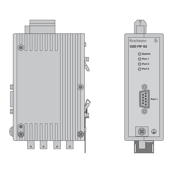
- Page 1 Handbuch Fiberoptic FIP-Repeater OZD FIP G3 … Manual Fiber-Optic FIP Repeater OZD FIP G3 … Manuel Interface FIP pour Fibre Optique OZD FIP G3 … OZD FIP G3 System Port 1 Port 2 Port 3 Port 1...
- Page 2 Seite / Page / Page Deutsch 1 – 20 English 21 – 40 Français 41 – 60...
-
Page 3: Port
Handbuch Fiberoptic FIP-Repeater OZD FIP G3 … OZD FIP G3 System Port 1 Port 2 Port 3 Port 1... - Page 4 – Ausbildung oder Unterweisung gemäß den aktuellen Sie die erforderliche Auskunft über den Hirschmann- Standards der Sicherheitstechnik in Pflege und Vertragspartner in Ihrer Nähe oder direkt bei Hirschmann Gebrauch angemessener Sicherheitsausrüstungen; (Adresse siehe im Abschnitt „Hinweis zur CE-Kennzeich- nung“) anfordern.
-
Page 5: Port
Das Gerät darf nur für die im Katalog und in der Wählen Sie den Montageort so, dass die in den Tech- technischen Beschreibung vorgesehenen Einsatz- nischen Daten angegebenen klimatischen Grenzwerte fälle und nur in Verbindung mit von Hirschmann eingehalten werden. empfohlenen bzw. zugelassenen Fremdgeräten und -komponenten verwendet werden. Der ein-... - Page 6 Mitgliedstaaten über die elektromagneti- sche Verträglichkeit (geändert durch RL 91/263/EWG, 92/31/EWG und 93/68/EWG). Die EU-Konformitätserklärung wird gemäß der obenge- nannten EU-Richtlinien für die zuständigen Behörden zur Verfügung gehalten bei: Hirschmann Automation and Control GmbH Stuttgarter Strasse 45-51 72654 Neckartenzlingen Abteilung AM Telefon 01805-141538 E-Mail hac-support@hirschmann.de...
-
Page 7: Table Of Contents
Inhalt Inhalt 1 Einführung ............. . . 2 Netztopologien . -
Page 9: Einführung
1 Einführung 1 Einführung Der Fiberoptic FIP-Repeater OZD FIP G3 … ist für den Zur Erhöhung der Betriebssicherheit ist eine redundante Einsatz in optischen FIP-Feldbusnetzen vorgesehen. Betriebsspannungsversorgung aus zwei getrennten Er ermöglicht die Umsetzung von elektrischen in optische Quellen vorgesehen. Hierzu können die beiden Betriebs- FIP-Schnittstellen und umgekehrt. - Page 10 1 Einführung Glasfasertechnik FIP-Protokoll Der Einsatz der Glasfaserübertragungstechnik ermöglicht In einer Netztopologie entsprechend Abb. 2, 3 und 4 sehr große Reichweiten und bewirkt einen optimalen (Kap. 2) muss am Arbiter und in den Endgeräten eine Schutz vor EMV-Einwirkungen sowohl auf die Übertra- Antwortzeit berücksichtigt werden.
-
Page 11: Netztopologien
2 Netztopolgien 2.1 Optischer Ring mit Redundanz (Zweifaserring) 2 Netztopolgien 2.1 Optischer Ring mit Redundanz (Zweifaserring) Diese Netztopologie wird bei einer optischen Verbindung Die Repeater erkennen den Ausfall einer optischen von Endgeräten oder Bussegmenten angewendet. Strecke. Die Port-LED der unterbrochenen Strecke wird Durch den Einsatz einer redundanten Verbindung mit ausgeschaltet und durch Aufleuchten der roten System- OZD FIP G3 …... - Page 12 2 Netztopolgien 2.1 Optischer Ring mit Redundanz (Zweifaserring) Ergeben sich beim Aufbau eines redundanten optischen übernächsten Repeater miteinander zu verbinden. Rings in der Praxis durch zu lange LWL-Teilstrecken Am Anfang und am Ende einer so erzeugten Linie sind Probleme, so kann die Verkabelung auch wie in Abbil- jeweils zwei benachbarte Repeater miteinander zu dung 3 ausgeführt werden.
-
Page 13: Linientopologie Ohne Redundanz
2 Netztopolgien 2.2 Linientopologie ohne Redundanz 2.2 Linientopologie ohne Redundanz Diese Netztopologie wird bei einer optischen Verbindung von Endgeräten oder Bussegmenten angewendet. Der erste und letzte Repeater der Linie sollte mit einem „optischen Kurzschluss“ (siehe Abb. 4) abgeschlossen sein. Hierzu werden Ein- und Ausgang der freien Ports jeweils über ein kurzes LWL-Kabel mit BFOC-Steck- verbindern verbunden. - Page 14 2 Netztopolgien OZD FIP G3 … Version 3.2 08/07...
-
Page 15: Inbetriebnahme
3 Inbetriebnahme 3.1 Anschließen der optischen Busleitungen 3 Inbetriebnahme 3.1 Anschließen der optischen Busleitungen Verbinden Sie die einzelnen Repeater über ein Duplex ® LWL-Kabel mit BFOC/2,5 (ST ) Steckverbindern. Beachten Sie die maximale Länge der LWL-Kabel sowie die möglichen Fasertypen, die in den Techni- schen Daten angegeben sind. - Page 16 3 Inbetriebnahme 3.2 Montieren der Repeater Montieren auf eine Hutschiene ebenen Unterlage, z. B. auf der Montageplatte eines Schaltschrankes. Hängen Sie die oberen Rasthaken des Repeaters in die Hutschiene ein und drücken Sie die Unterseite, Versehen Sie die Montageplatte mit drei Bohrungen wie in der Abbildung 7 gezeigt, auf die Schiene, bis entsprechend dem Bohrschema in Abb.
-
Page 17: Anschließen Der Elektrischen Busleitungen
3 Inbetriebnahme 3.3 Anschließen der elektrischen Busleitungen 3.3 Anschließen der elektrischen Busleitungen Verwenden Sie als FIP-Busleitung nur Busleitungen Terminierung nach French Standard NF-C 46-604. OZD FIP G3: Der elektrische Port ist intern nicht terminiert. Die externe Terminierung ist im oder am Die elektrische FIP-Schnittstelle (Port 1) ist als 9poliger Steckverbinder der Busleitung laut French Standard Sub-D-Anschluss (male) ausgeführt. -
Page 18: Anschließen Der Meldekontaktleitungen
3 Inbetriebnahme 3.5 Anschließen der Meldekontaktleitungen +24 V/48 V Error +24 V/48 V* Befestigungs- flansch Abb. 10: Betriebsspannungsversorgung – Anschlussbelegung 5poliger Klemmblock 3.5 Anschließen der Meldekontaktleitungen Am 5poligen Klemmblock an der Repeateroberseite Grenzwerte des Relaiskontaktes stehen potenzialfreie Anschlüsse eines Relais als –... -
Page 19: Led-Anzeigen
4 LED-Anzeigen 4 LED-Anzeigen System grün: Repeater in Betrieb, Datenverkehr findet statt OZD FIP G3 rot: – Ausfall der Empfangsdaten am Port 2 System und/oder Port 3 (z.B. Kabelbruch) – keine Empfangsdaten am Port 1 nach dem Port 1 Anlegen der Spannung bzw. nach einem Port 2 Fehlerfall (das Gerät prüft nach dem Anlegen Port 3... -
Page 20: Hilfe Bei Betriebsstörungen
5 Hilfe bei Betriebsstörungen 5 Hilfe bei Betriebsstörungen LED-Anzeige Mögliche Fehlerursachen Meldekontakt System – Versorgungsspannung ausgefallen meldet – interner Gerätefehler – keine Empfangsdaten am Port 2 und/oder Port 3, z.B. Kabelbruch meldet – keine Empfangsdaten am Port 1, z.B. kein Teilnehmer an Port 1 –... -
Page 21: Technische Daten
6 Technische Daten 6 Technische Daten Repeater OZD FIP G3 (GS) OZD FIP G3 T Bestell-Nr. 933 847-421 (933 847-001) 933 847-521 Spannungs-/Stromversorgung Betriebsspannung +24 V –20 % bis +48 V +10 %, verpolungssicher Sicherheitskleinspannung Stromaufnahme bei +24 V 150 mA bei +48 V 85 mA Leistungsaufnahme bei +24 V... -
Page 22: Applikationsunterstützung
500 g Abmessungen 40 x 133 x 77 mm Gehäusewerkstoff Zink-Druckguss/Alu-Blech 7 Applikationsunterstützung Kontaktadresse für technische Unterstützung Hirschmann Automation and Control GmbH Stuttgarter Strasse 45 - 51 72654 Neckartenzlingen Germany/Allemagne Tel.: +49 / 1805/ 14-1538 Fax: +49 / 7127/ 14-1551 E-Mail: hac-support@hirschmann.de... - Page 23 Manual Fiber-Optic FIP Repeater OZD FIP G3 … OZD FIP G3 System Port 1 Port 2 Port 3 Port 1...
- Page 24 We would point out that the content of these operating instructions is not part of, nor is it intended to amend an earlier or existing agreement, permit or legal relation-ship. All obligations on Hirschmann arise from the respective Staff qualification requirements purchasing agreement which also contains the full war- Note: ranty conditions which have sole applicability.
- Page 25 (IEC 60664-1). and only in conjunction with external devices and components recommended or approved by Hirschmann. The product can only be operated correctly and safely if it is transported, stored, Safety Guideline Housing installed and assembled properly and correctly.
- Page 26 (amended by Directives 91/263/EEC, 92/31/EEC and 93/68/EEC). The EU declaration of conformity is kept available for the responsible authorities in accordance with the above- mentioned EU directives at: Hirschmann Automation and Control GmbH Stuttgarter Strasse 45-51 72654 Neckartenzlingen Germany Telephone...
- Page 27 Contents Contents 1 Introduction ............. . 2 Network Topologies .
-
Page 29: Introduction
1 Introduction 1 Introduction The fiber-optic FIP repeater OZD FIP G3 … is designed A redundant power supply from two separate sources is for use in optical FIP field bus networks. It permits provided to increase operational reliability. The two ope- conversions of electrical FIP interfaces into optical rating voltages can be supplied to two different terminals FIP interfaces and vice versa. - Page 30 1 Introduction Fiber-optic technology FIP protocol The implementation of fiber-optic technology permits In a network topology as shown in Fig. 2, 3 and 4 (Ch. 2), a very long transmission ranges and provides optimum response time must be taken into consideration at the protection against EMI effects both along the trans- arbiter and in the data terminal equipment.
-
Page 31: Network Topologies
2 Network Topologies 2.1 Redundant optical ring (two-fiber ring) 2 Network Topologies 2.1 Redundant optical ring (two-fiber ring) This network topology is used in the case of an optical The repeaters detect failure of an optical link. The port link between data terminal units or bus segments. LED of the faulty link is deactivated and the failure is The implementation of a redundant link with OZD FIP G3 …... - Page 32 2 Network Topologies 2.1 Redundant optical ring (two-fiber ring) If problems are encountered with the configuration the next repeater but one. Two adjacent repeaters must of a redundant optical ring on account of excessively be interconnected at the start and end of every such line. long fiber-optic line sections, connections can also be This avoids individual “excessively long“...
-
Page 33: Line Topology Without Redundancy
2 Network Topologies 2.2 Line topology without redundancy 2.2 Line topology without redundancy This network topology is used in the case of an optical link between data terminal units or bus segments. The first and last repeater in the line should be terminated with an “optical short-circuit“... - Page 34 2 Network Topologies OZD FIP G3 … Version 3.2 08/07...
-
Page 35: Setting Up
3 Setting Up 3.1 Connection of optical bus lines 3 Setting Up 3.1 Connection of optical bus lines ® Use a duplex fiber-optic cable with BFOC/2.5 (ST connectors to connect the individual repeaters. Pay attention to the maximum cable length of the fiber-optic cable as well as the possible types of fibers specified in the Technical Data. - Page 36 3 Setting Up 3.2 Mounting repeaters Mounting on DIN rail Make three holes in the mounting plate corresponding to the drilling template in Fig. 8. Engage the upper snap-in hooks of the repeater in Secure the repeaters with machine bolts (e.g. the DIN rail and press the underside (as shown M 3 x 40).
-
Page 37: Connection Of Electrical Bus Lines
3 Setting Up 3.3 Connection of electrical bus lines 3.3 Connection of electrical bus lines Only bus lines to the French Standard NF-C 46-604 Termination should be used as the FIP bus line. OZD FIP G3: The electrical port is not internally termi- nated. -
Page 38: Connection Of Signaling Contact Lines
3 Setting Up 3.5 Connection of signaling contact lines +24 V/48 V Error +24 V/48 V* Securing flange Fig. 10: Operating voltage supply - assignment of 5-pole terminal block 3.5 Connection of signaling contact lines At the 5-pole terminal block on the upper side of the Limit values of relay contact repeater, floating contacts of a relay are provided as –... -
Page 39: Led Indicators
4 LED Indicators 4 LED Indicators System Green: Repeater in operation, data traffic occurring OZD FIP G3 Red: – No data received at Port 2 and/or Port 3 System (e.g. cable breakage) – not data received at Port 1 after impressing Port 1 the operating voltage resp. -
Page 40: Troubleshooting
5 Troubleshooting 5 Troubleshooting LED indicator Possible causes Signaling contact System Not lit – Failure of supply voltage Signal – Internal device fault – No data received at Port 2 and/or Port 3, e.g. cable breakage Signal – No data received at Port 1, e.g. no participant at Port 1 –... -
Page 41: Technical Data
6 Technical Data 6 Technical Data Repeater OZD FIP G3 (GS) OZD FIP G3 T Ord. code 933 847-421 (933 847-001) 933 847-521 Voltage/power supply Operating voltage +24 V –20 % to +48 V +10 %, non-interchangeable Safety extra-low voltage Current consumption for +24 V 150 mA... -
Page 42: Application Support
500 g Dimensions 40 x 133 x 77 mm Housing material Die-cast zinc/sheet aluminum 7 Application Support Contact address for technical support Hirschmann Automation and Control GmbH Stuttgarter Strasse 45 - 51 72654 Neckartenzlingen Germany/Allemagne Tel.: +49 / 1805-1538 Fax: +49 / 7127/ 14-1551 E-Mail: hac-support@hirschmann.de... - Page 43 Manuel Interface FIP pour Fibre Optique OZD FIP G3 … OZD FIP G3 System Port 1 Port 2 Port 3 Port 1...
- Page 44 Toutes les obligations incom- Exigences relatives à la qualification du bant à Hirschmann découlent du contrat de vente conclu personnel lors de l’acquisition de l’appareil, où figurent également Remarque: les clauses intégrales, et seules valables, de garantie.
- Page 45 Hirschmann. Le Utilisation seulement dans un environnement d’un fonctionnement exempt de défauts et sûr du pro- degré de pollution 2 (IEC 60664-1).
- Page 46 électromagnétique (modifiée par les directives 91/263/CEE 92/31/CEE et 93/68/CEE). Conformément aux directives UE susmentionnées, la déclaration de conformité UE est mise à la disposition des autorités compétentes à: Hirschmann Automation and Control GmbH Stuttgarter Strasse 45-51 72654 Neckartenzlingen Allemagne Telefon...
- Page 47 Sommaire Sommaire 1 Introduction ............. . 2 Topologies de réseaux .
-
Page 49: Introduction
1 Introduction 1 Introduction L’interface FIP pour fibres optiques OZD FIP G3 … a été Une alimentation en tension de fonctionnement redon- conçu pour être utilisé dans des réseaux de bus de dante issue de deux sources différentes est prévue pour terrain FIP. - Page 50 1 Introduction Technique de fibre de verre Protocole FIP L’utilisation de la technique de transmission par fibres Dans une topologie correspondant aux figures 2, 3 et 4 de verre permet de couvrir une très grande portée et (chapitre 2), un temps de réponse doit être pris en compte offre une protection optimale contre les effets de la sur l’Arbitre et sur les terminaux.
-
Page 51: Topologies De Réseaux
2 Topologies de réseaux 2.1 Boucle optique avec redondance (boucle biphasée) 2 Topologies de réseaux 2.1 Boucle optique avec redondance (boucle biphasée) Cette topologie de réseau est utilisée pour réaliser une Les interfaces identifient la défaillance d’une voie optique. liaison optique de terminaux ou de segments de bus. La DEL du port de la voie interrompue est désactivée Il est possible d’obtenir une grande sécurité... - Page 52 2 Topologies de réseaux 2.1 Boucle optique avec redondance (boucle biphasée) Si des problèmes surgissent en pratique lors de l’établis- Chaque interface doit être, vu dans l’espace, raccordé sement d’une boucle optique redondante, dus à des à la suite du prochain interface. Les interfaces voisins trajets partiels de cables à...
-
Page 53: Topologie De Lignes Sans Redondance
2 Topologies de réseaux 2.2 Topologie de ligne sans redondance 2.2 Topologie de ligne sans redondance Cette topologie de réseau est utilisée pour raccorder de manière optique des terminaux ou des segments de bus. Le premier et le dernier interface de la ligne doit être terminés par un ”court-circuit optique“... - Page 54 2 Topologies de réseaux OZD FIP G3 … Version 3.2 08/07...
-
Page 55: Mise En Service
3 Mise en service 3.1 Raccordement des lignes de bus optiques 3 Mise en service 3.1 Raccordement des lignes de bus optiques Raccorder les différents interfaces au moyen d’un câble à fibres optiques duplex doté de connecteurs ® BFOC/2,5 (ST Respecter la longueur maximale du câble à... - Page 56 3 Mise en service 3.2 Montage des interfaces Montage sur un rail DIN plat quelconque, la plaque de montage d’une armoire de commande par exemple. Suspendre le crochet de verrouillage supérieur du interface dans le rail DIN et exercer une pression sur Réaliser trois orifices dans la plaque de montage, la partie inférieure du profilé, de la manière indiquée conformément au schéma de perçage représenté...
-
Page 57: Raccordement Des Lignes De Bus Électrique
3 Mise en service 3.3 Raccordement des lignes de bus électrique 3.3 Raccordement des lignes de bus électrique Pour les lignes de bus, utiliser exclusivement des Terminaison lignes FIP normées, conformes au standard français OZD FIP G3: Le port électrique n’est pas terminé sur NF-C 46-604. -
Page 58: Raccordement Des Lignes Des Contact De Signalisation
3 Mise en service 3.5 Raccordement des lignes du contact de signalisation +24 V/48 V Erreur +24 V/48 V* Bride de fixation Fig. 10: Tension d’alimentation et schéma de raccordement 5 pôles sur le bornier 3.5 Raccordement des lignes du contact de signalisation Le raccordement du contact, libre de potentiel, du Valeurs limite du contact de relais office de contact de signalisation se trouvent sur le... -
Page 59: Affichages Par Del
4 Affichages par DEL 4 Affichages par DEL Système Vert: L’interface fonctionne, l’échange des données OZD FIP G3 est en cours System Rouge: – Défaillance des données de réception sur le port 2 et/ou sur le port 3 (par ex. bris de Port 1 câble) Port 2... -
Page 60: Dépannage
5 Dépannage 5 Dépannage Affichage DEL Erreur possible Contact de signalisation Système Eteinte – Tension d’alimentation défaillante Ouvert (N.O) – Erreur interne de l’appareil Rouge – Pas de données de réception sur le port 2 et/ou sur le port 3, Ouvert (N.O) par ex bris de câble –... -
Page 61: Caractéristiques Techniques
6 Caractéristiques techniques 6 Caractéristiques techniques Repeater OZD FIP G3 (GS) OZD FIP G3 T N° de cde. 933 847-421 (933 847-001) 933 847-521 Alimentation de tension/en courant Tension de fonctionnement +24 V –20 % à +48 V +10 %, protégée contre inversion de pôles, basse tension de sécurité... -
Page 62: Références Utiles
40 x 133 x 77 mm Matériau du boîtier zinc moulé sous pression/ tôle d’aluminium 7 Références utiles Adresse de l'assistance technique Hirschmann Automation and Control S.A.S. 2, Rue des Charpentiers 95330 Domont France Tel.: +33 / 1-39 35 01 00... - Page 63 Hirschmann Automation and Control GmbH Stuttgarter Strasse 45 - 51 72654 Neckartenzlingen Germany/Allemagne Tel.: +49 / 1805-1538 Fax: +49 / 7127/ 14-1551 E-Mail: hac-support@hirschmann.de Internet: http://www.hirschmann.com 933 847-901-05-0807 Printed in Germany...
Need help?
Do you have a question about the OZD FIP G3 Series and is the answer not in the manual?
Questions and answers