
Related Manuals for Hirschmann OZD Profi 12M G12 PRO


Summary of Contents for Hirschmann OZD Profi 12M G12 PRO
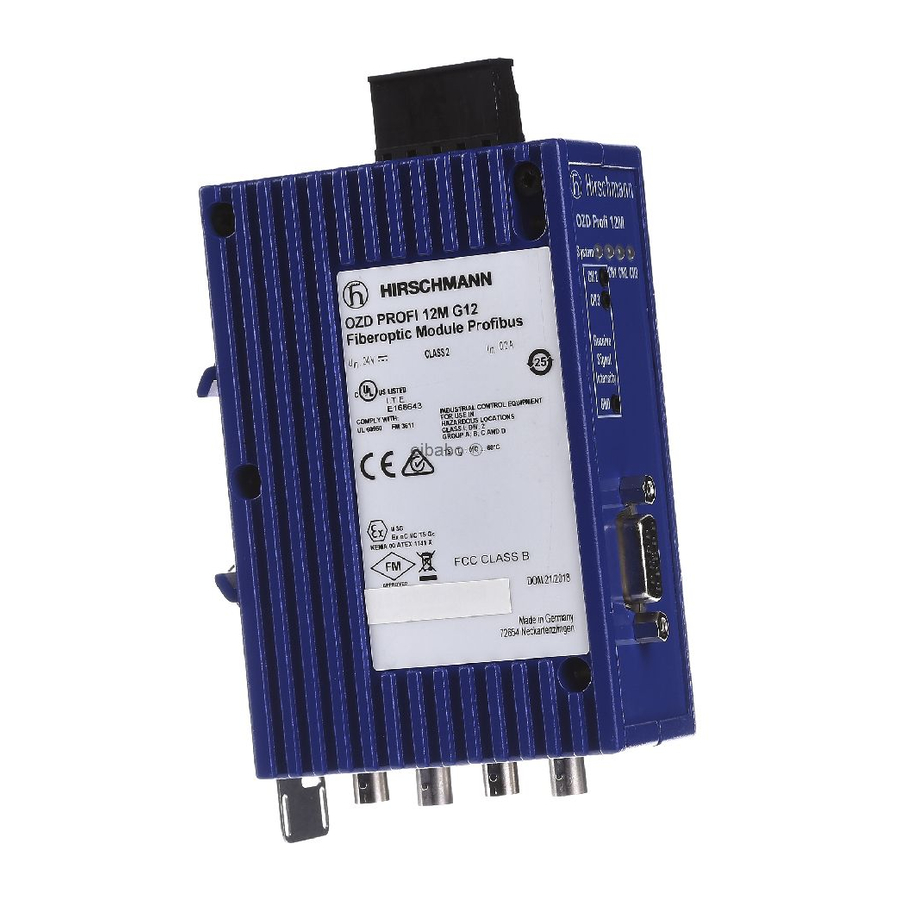
- Page 1 Manual PROFIBUS Rail Repeater OZD Profi 12M G12 ... PRO OZD Profi 12M PR0 CH1 CH2 CH3 System Receive Signal Intensity...
- Page 2 You can get the latest version of this manual on the Internet at the of the company's knowledge. Hirschmann product site (www.hirschmann.com). Hirschmann reserves the right to amend the contents of this Description and Operating Instructions without prior notice. Hirschmann cannot provide any warranty or guarantee with regard to the correctness or accuracy of the information contained in this Description and Operating Instructions.
-
Page 3: Table Of Contents
Contents Contents Safety Instructions ..............1 Introduction . - Page 4 Contents 5 Help with problems ..............35 LED displays .
-
Page 5: Safety Instructions
Safety Instructions Notes on safety General safety instructions This manual contains instructions to be observed for This device is operated by electricity. You must follow ensuring your personal safety and for preventing damage. precisely the prescribed safety requirements in the The warnings appear next to a warning triangle with a operating manual that relate to the voltage connect - different heading depending on the degree of danger... - Page 6 Safety instructions for housing – Interference emissions: EN 55022:1998+A1:2000+A2:2003 Class A Warning! Only technicians authorized by Hirschmann are Warning! permitted to open the housing. This is a Class A device. This equipment may cause radio interference if used in a residential area;...
- Page 7 Safety Instructions Operation is subject to the following two conditions: ATEX RL 94/9EG Zone 2 3G Please note the important information in: Chapter 4.2 (1) This device may not cause harmful interference, and ”Use in Ex-zone 2 according to ATEX RL 94/9EG“, (2) This device must accept any interference received, page 23.
-
Page 8: Introduction
OZD Profi 12M P12 PRO, Housing OZD Profi 12M G11 PRO, OZD Profi 12M G12 PRO, The housing consists of two plastic sections and a front OZD Profi 12M G12 EEC PRO, panel made of metal. It can be mounted on a DIN rail. - Page 9 1 Introduction Glass fiber technology Measuring output The use of glass fiber transmission technology enables One measuring output is available for each optical chan- a very large transmission range and ensures optimal nel at the 3-pin screw terminal block on the front of the protection from EMC effects on the transmission path repeater.
- Page 10 1 Introduction Transmission speed Compatibility with other PROFIBUS repeaters The PROFIBUS-Repeater OZD Profi 12M … PRO The devices are fully compatible with the repeaters of the supports data rates from 9.6 kBit/s to 12 Mbit/s. previous generation of OZD Profi 12M … and can be combined with them.
-
Page 11: General Functions
2 General Functions 2.1 Non operating mode related functions 2 General Functions 2.1 Non operating mode related functions Transmission rate Signal regeneration The OZD Profi 12M … PRO support all the transmission The repeaters regenerate the signal form and amplitude speeds (transmission rates) defined in the EN 50170 of the data received. -
Page 12: Operating Mode Related Functions
2 General Functions 2.2 Operating mode related functions 2.2 Operating mode related functions The operating mode is set using switches located on the Monitor echo front of the repeater. A sticker attached to the side of the If a repeater sends a frame - no echo! – to an optical repeater provides assistance with the settings. -
Page 13: Network Topologies
3 Network Topologies 3.1 Line topology 3 Network Topologies The following network topologies can be realized with the In areas with a high EMC incidence, only lay opti- OZD Profi 12M … PRO: cal fiber lines in order to exclude the possibility of EMC affecting the whole network. -
Page 14: Line Topology With Optical Fiber Link Monitoring And Segmentation
3 Network Topologies 3.1 Line topology In a line structure, the individual OZD Profi 12M … PRO Please note that the following ambient conditions must are connected together by dual-fiber optical fibers. be fulfilled to ensure that network configuration functions Repeaters with one optical channel are sufficient at the correctly: beginning and end of a line, between which repeaters with... -
Page 15: Line Topology Without Optical Fiber Link Monitoring
3 Network Topologies 3.1 Line topology 3.1.2 Line topology without optical fiber link monitoring Use this operating mode if you connect a OZD Profi 12M … PRO with another optical fiber network component, which does not send a frame echo and does not expect or is not compatible with a frame echo in accordance with PROFIBUS guidelines (optical/electrical converter). - Page 16 3 Network Topologies 3.2 Redundant ring This network topology represents a special form of line If a redundancy case occurs (e.g. a line break), topology. A high degree of network operating safety is there is a switching time during which data cannot achieved by ”closing“...
-
Page 17: Star Topology
3 Network Topologies 3.3 Star topology 3.3 Star topology Electrical star segment OZD … OZD … OZD … OZD … P11 PRO P12 PRO P11 PRO P11 PRO G11 (-1300) PRO G12 (-1300) PRO G11 (-1300) PRO G11 (-1300) PRO Ch 1 Ch 1 Ch 1... - Page 18 3 Network Topologies 3.3 Star topology Ensure that the electrical star segment is wired If the link monitoring on the optical channels is activated, the fiber optic links are monitored by the respectively carefully. Keep it as small as possible to avoid interference injection into the electrical star connected OZD Profi 12M …...
-
Page 19: Setting Up
4 Setting Up 4.1 Installation guidelines 4 Setting Up 4.1 Installation guidelines Electromagnetic compatibility (EMC) Electromagnetic compatibility (EMC) covers all aspects The structural design and correct connection of bus lines regarding the effects of radiated and received electrical, as well as the interference suppression of switched magnetic, and electromagnetic emissions. - Page 20 4 Setting Up 4.1 Installation guidelines Standard recommendations for the arrangement of - In the case of steady-state operation, it is advisable devices and cables: to strip the shielded line entirely and connect it with EN 50174–2 contains recommendations for arranging the shielding bus /protective conductor rail.
- Page 21 4 Setting Up 4.1 Installation guidelines Laying cables inside of buildings Situations where interference can present a problem include: Laying cables within control cabinets - Plant which extends over a large area If a repeater is installed within a control cabinet, the cable - Power is fed to the plant from different power sources shield of the incoming bus cable should be electrically - Networking extends over several buildings...
- Page 22 4 Setting Up 4.1 Installation guidelines Laying cables outside of buildings for outside installation, the cables should be provided with additional protection by laying them Warning! inside a suitable plastic pipe. It is recommended to use fiber optic cables for bus installations which are outside of buildings.
-
Page 23: Use In Ex Zone 2 According To Atex 94/9/Eg
4 Setting Up 4.2 Use in Ex zone 2 according to ATEX 94/9/EC 4.2 Use in Ex zone 2 according to ATEX 94/9/EC Relevant information for use in Ex zone 2 Special conditions for safe use according to ATEX 94/9/EC The modules shall be installed in a suitable enclosure in accordance with EN60079-15, taking into account the This product may be operated in EX zone 2 only if the... - Page 24 4 Setting Up 4.3 Use in North America CONTROL DRAWING: Hazardous Locations Class I Division 2 Groups A, B, C, D HAZARDOUS LOCATION Non Hazardous Location Fault contacts. (Short: o.k., Open: fault) Equipment with nonincendive Fault field wiring parameters: = 30 V = 90 mA Power supply (Redundant) +24V (P1)
-
Page 25: Installation Procedure
4 Setting Up 4.4 Installation procedure 4.4 Installation procedure The Repeater OZD Profi 12M … PRO is installed by the Installing repeater following steps: Setting compatibility, operating mode and transmitting power Connecting the optic bus cables Connecting the electric bus cables Connecting the function ground and the shield of the bus cable Connecting the signal contact lines (optional) -
Page 26: Installing Repeater
4 Setting Up 4.5 Installing repeater 4.5 Installing repeater The Fiberoptic Repeater OZD Profi 12M … PRO can be mounted on a 35 mm DIN rail in accordance with IEC 60715: 1981 + A1: 1995. Install the device in a location where the climatic threshold values specified in the technical data are adhered to. -
Page 27: Setting Compatibility, Operating Mode And Transmitting Power
4 Setting Up 4.6 Setting compatibility, operating mode and transmitting powerpower 4.6 Setting compatibility, operating mode and transmitting power Please note: The OZD Profi 12M … PRO must be switched off when changing the operating mode. You can switch off the OZD Profi 12M … PRO by, e.g., unplugging the 7-pin terminal block. -
Page 28: Setting The Operating Mode
4 Setting Up 4.6 Setting compatibility, operating mode and transmitting powerpower 4.6.2 Setting the operating mode Achtung! Die folgenden Angaben gelten nur für die Defaultstellung von S7 (S7 = 0)! The DIL switch S0 is used to set the operating mode The DIL switches S3 and S4 are used to set the of the electrical channel CH1. -
Page 29: Reducing The Optical Transmitting Power
4 Setting Up 4.6 Setting compatibility, operating mode and transmitting powerpower Operating mode ”Redundant optical ring“ CH 3 CH 2 CH 3 CH3 is activated in this operating mode Note: This operating mode must always be set at both of if S3 and S4 are in Position 1. -
Page 30: Connecting The Optic Bus Cables
4 Setting Up 4.7 Connecting the optic bus cables 4.7 Connecting the optic bus cables Connect the individual repeaters using a duplex F/O ® cable with BFOC/2.5 (ST ) connectors. Note the maximum length of the F/O cables and the possible fiber types specified in the technical data. - Page 31 4 Setting Up 4.9 Connecting the electric bus cables Only use shielded and twisted-pair wiring as a RS 485 Attach or remove the RS 485 bus connector plug bus line. quickly and without twisting them. Use a PROFIBUS bus connector plug to connect the Remove the RS 485 bus line from the OZD Profi if a RS 485 bus segment.
-
Page 32: Connecting The Function Ground And The Shield Of The Bus Cable
4 Setting Up 4.9 Connecting the function ground and the shield of the bus cable 4.9 Connecting the function ground and the shield of the bus cable Note: this could destroy the repeaters. Use F/O cables for bus connections outside buildings! See chapter “Laying cables outside of buildings”... -
Page 33: Connecting The Analog Voltage Outputs (Optional)
4 Setting Up 4.11 Connecting the analog voltage outputs (optional) 4.11 Connecting the analog voltage outputs (optional) The device has two analog voltage outputs, CH2 and CH3, each of which supplies a short-circuit-proof output Receive voltage dependent on the optical power input at channel Signal 2 or channel 3, for diagnosis purposes and, for example, Intensity... -
Page 34: Connecting The Operating Voltage Supply
4 Setting Up 4.11 Connecting the analog voltage outputs (optional) Notes: channel with a voltage derived from the peak value of the For a measured value to be valid, it is necessary that the optical Profibus telegram without disrupting the commu- partner OZD Profi on the other end of the optical fiber nication of data. -
Page 35: Help With Problems
5 Help with problems 5.1 LED displays 5 Help with problems 5.1 LED displays OZD Profi 12M PR0 CH1 CH2 CH3 System Fig. 15: LED indicators on the front panel LED display Possible causes Signal contact System lights green – The transmission rate has been recognized and the power supply is in order no signal not lit –... - Page 36 5 Help with problems 5.1 LED displays LED display Possible causes Signal contact lights yellow Signals are being received on the RS 485 bus line. no signal electric not lit – Bus subscriber is not connected no signal – Connected bus subscriber is not switched on –...
-
Page 37: Troubleshooting
5 Help with problems 5.2 Troubleshooting 5.2 Troubleshooting 5.2.1 Troubleshooting after signaling via Fault indicated on CH2 / CH3 LED or signal contact Check the following: optically only repeaters of the same type are con - This chapter helps you to localize faults after they have nected together (see 3, ”Network topologies“, p. -
Page 38: Systematic Troubleshooting
5 Help with problems 5.2 Troubleshooting 5.2.2 Systematic troubleshooting Configuration (these settings can usually be set on the PROFIBUS master using configuration software, not on the OZD Profi 12M … PRO): This chapter helps you to localize an error systematically - Slot time configured correctly? (for basics, see with the help of the following questions. -
Page 39: Problem Reporting
You can get the current version of this manual on the Internet at http://www.hirschmann.com via the product 5. Give as detailed a description of the error as possible search at the product. -
Page 40: Contact Address
5 Help with problems 5.4 Contact Address 5.4 Contact address Contact address for technical support Hirschmann Automation and Control GmbH Stuttgarter Strasse 45 - 51 72654 Neckartenzlingen Germany Tel.: +49 (0)1805 14-1538 Fax: +49 (0)7127 14-1551 E-mail: HAC.Support@Belden.com Internet: http://www.hirschmann.com... -
Page 41: Configuration
6 Configuration 6.1 Configuration of redundant optical rings 6 Configuration During configuration, the PROFIBUS network parameter caused by lines and network components, as well as by "Slot time" must be adapted to the network coverage, monitoring mechanisms in the network components. network topology and the data rate due to frame delays 6.1 Configuration of redundant optical rings The following configuration conditions must be fulfilled in... - Page 42 6 Configuration 6.1 Configuration of redundant optical rings The calculation of the slot time only takes into considera- Note: tion the optical network and the connection of bus sub - When the slot time is configured with a too small value scribers to the OZD Profi via an RS 485 bus segment the OZD Profi 12M …...
-
Page 43: Technical Data
7 Technical Data 7 Technical Data OZD Profi 12M … PRO G11-1300 G12-1300 G12-EEC G12-1300 EEC Voltage/power supply Operating voltage NEC Class 2 power source 18 ... 32 V DC (24 V DC typ.) safety extra-low voltage (SELV/PELV); (redundant inputs decoupled), 5 A max., buffer time min. - Page 44 7 Technical Data OZD Profi 12M … PRO G11-1300 G12-1300 G12-EEC G12-1300 EEC Transmission distance – with glass fiber E 10/125 (Default) (0.5 dB/km) – – 0 - 15 000 m – with glass fiber G 50/125 (Default) (860 nm: 3.0 dB/km; 1310 nm: 1.0 dB/km) –...
- Page 45 7 Technical Data OZD Profi 12M … PRO G11-1300 G12-1300 G12-EEC G12-1300 EEC Mechanical ambient conditions Vibrations 3 to 9 Hz, 3,5 mm amplitude 9 to150 Hz, 1 g acceleration Frequency change: 1 octave / min 10 cycles per axis along all 3 spatial axes In accordance with IEC 60068-2-6, test Fc Shock 15 g half-sine for 11 ms...
- Page 46 Hirschmann Automation and Control GmbH Stuttgarter Strasse 45 - 51 72654 Neckartenzlingen Germany Tel.: +49 (0)1805 14-1538 Fax: +49 (0)7127 14-1551 E-mail: HAC.Support@Belden.com Internet: http://www.hirschmann.com 039 690-001-E-04-0514 Printed in Germany...
Need help?
Do you have a question about the OZD Profi 12M G12 PRO and is the answer not in the manual?
Questions and answers