
Related Manuals for Hirschmann OZD Profi 12M


Summary of Contents for Hirschmann OZD Profi 12M
- Page 1 Manual PROFIBUS Repeater OZD Profi 12M … OZD Profi 12M System CH 1 CH 2 CH 3 CH 2 CH 3 Receive Signal Intensity CH 1...
- Page 2 Description and Operating Instructions. Under no circumstances can Hirschmann be held liable for any damage arising from the use of the PROFIBUS-Repeater OZD Profi 12M … . © 2007 Hirschmann Automation and Control GmbH...
-
Page 3: Table Of Contents
4.4.2 Setting the operating mode ..........18 4.4.3 Reducing the optical transmitting power on the OZD Profi 12M P11 ....19 and OZD Profi 12M P12 Installation . - Page 4 Contents 8 Appendix ................33 FCC conformity .
-
Page 5: Introduction
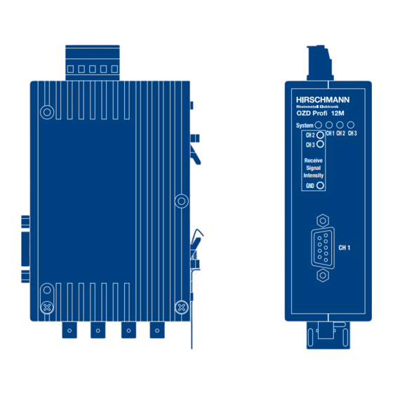
Intensity Port 1 CH 1 electric, Sub-D socket Port 2 Port 3 optical, optical, BFOC/2.5 BFOC/2.5 socket socket Fig.1: OZD Profi 12M … module showing the location of the LED indicators, measuring sockets and the individual ports. Version 2.4 04/07... - Page 6 The mechanical design consists of a compact, stable metal housing which can be mounted on a hat rail or OZD Profi 12M G12 and OZD Profi 12M G12-EEC have mounting plate as required. the same function. They only differ in the specification...
-
Page 7: General Functions
1.5 MBit/s, 3 MBit/s, 6 MBit/s and 12 MBit/s. PROFIBUS networks). The transmission rate is set automatically as soon as the OZD Profi 12M … receives a frame. The setting or ad- justment is dependent on the transmission rate and the Help when setting up set operating mode. - Page 8 2 General Functions 2.2 Operating mode related functions Line monitoring with echoes Segmentation The modules enable the connected optical paths to be If an echo monitoring error or a frame falsification arises actively monitored for interruptions in the fiber line by at an optical port, the module assumes that the line is means of the functions ”Send echo“, ”Monitor echo“...
-
Page 9: Network Topologies
– OZD Profi 12M P11 with … P12 If a malfunction – e.g. a break in a fiber line – makes a – OZD Profi 12M G11 with … G12 and …G12 EEC high degree of field bus network fail-safety necessary, –... -
Page 10: Line Topology With Optical Fiber Link Monitoring And Segmentation
3 Network Topologies 3.1 Line topology In a line structure, the individual OZD Profi 12M … are Please note that the following ambient conditions must connected together by dual-fiber optical fibers. Modules be fulfilled to ensure that network configuration functions... -
Page 11: Line Topology Without Optical Fiber Link Monitoring
3 Network Topologies 3.1 Line topology 3.1.2 Line topology without optical fiber link monitoring Use this operating mode if you connect a OZD Profi 12M … with another optical fiber network component, which does not send a frame echo and does not expect or is not compatible with a frame echo in accordance with PROFIBUS guidelines (optical/electrical converter). -
Page 12: Star Topology
CH1 in mode ”Monitor off“ (S0 = 1) must be acti- by dual-fiber optical fiber lines. The modules of the star vated on all OZD Profi 12M … which are connected coupler are connected to one another via the electrical to the electrical star segment. -
Page 13: Redundant Optical Ring
Ensure that the electrical star segment is wired the fiber optic links are monitored by the respectively carefully. Keep it as small as possible to avoid connected OZD Profi 12M …. interference injection into the electrical star segment, and from here into the entire network. - Page 14 An interruption of one or both optical fibers between two device whose address has been configured, but modules is detected by the OZD Profi 12M … and the which does not physically exist. ring is transformed into an optical line.
-
Page 15: Setting Up
4 Setting Up 4.1 Safety notice 4 Setting Up 4.1 Safety notice Only use the OZD Profi 12M … as described in DANGER: Never connect the OZD Profi 12M … to this ”Description and Operating Instructions“. the main power supply. -
Page 16: Notes On Ce Marking
Mode CH 2 Mode CH 1 +24 VDC Fault Fig. 5: Top view of the Module OZD Profi 12M – location of the DIL switches and terminal block for the operating power +24 VDC * supply/signaling contacts. The illustration shows the factory settings of the... -
Page 17: Setting Compatibility, Operating Mode And Transmitting Power
Mode Monitor Mode Monitor Line/Ring Line/Ring Only turn switch S7 to Position 1 if the OZD Profi 12M … Line Line Redundancy Redundancy is being used as a spare or expansion device in existing networks in conjunction with OZD Profi of the preceding... -
Page 18: Setting The Operating Mode
CH3. The DIL switches S1 and S2 are used to set the oper- S3 and S4 do not have a function on OZD Profi 12M … ating mode of the optical port CH2. with only one optical interface. -
Page 19: Reducing The Optical Transmitting Power On Theozd Profi 12M P11
Profi device when using plastic optical fiber cables to CH2. Note: The DIL switches S5 and S6 on the OZD Profi 12M … for The transmitting power default setting (S5 or S6 in glass optical fiber cables do not have a function (the Position 1) must be set when using PCF fibers. -
Page 20: Installation
) for the If the arrangement of the various elements in a OZD Profi 12M … must not be laid in the same building or in the switch cabinet is taken into con- cable duct as cables for load circuits. - Page 21 4 Setting Up 4.5 Installation Standard recommendations for the arrangement of - Attach the shield for the bus line at the connector devices and cables: plug housing or at the cable clamps provided. EN 50174–2 contains recommendations for arran- - In the case of steady-state operation, it is advisable ging devices and cables which are aimed at redu- to strip the shielded line entirely and connect it cing mutual interference to a minimum.
-
Page 22: Connecting The Optical Lines
2 and 3 (device with two optical ports). 4.5.3 Mounting the modules The OZD Profi 12M … modules can either be mounted Connect the optical fiber line before mounting the on a 35 mm hat rail in accordance with DIN EN 50022 module. - Page 23 The modules have three through-holes. This allow it to be mounted on any flat surface, e.g. on the mounting plate of a switch cabinet. 61.2 mm OZD Profi 12M System Drill three holes in the mounting plate corresponding CH 1...
-
Page 24: Connecting The Electric Rs 485 Bus Lines
2. Attach the RS 485 bus connector plug to the both ends to connect a single device. OZD Profi 12M … quickly and without twisting the All PROFIBUS bus connector plugs in a network must connector, and screw it on tightly. -
Page 25: Connecting The Power Supply
4 Setting Up 4.5 Installation 4.5.5 Connecting the power supply The terminal block can be removed from the device to L1+ / +24 VDC connect the lines. The module should only be supplied with a regulated safety extra-low voltage in accordance with IEC 950/EN 60 950/VDE 0805 with a maximum of +32 VDC (typical +24 VDC). -
Page 26: Defining The Receiving Level Of The Optical Ports
2 mm laboratory test plugs. The OZD Profi 12M … is protected against short circuits at the measuring sockets, although data transmission OZD Profi 12M may be briefly disrupted.*... -
Page 27: Led Indicators And Troubleshooting
5 LED Indicators and Troubleshooting 5.1 LED Indicators 5 LED Indicators and Troubleshooting 5.1 LED Indicators OZD Profi 12M LED indicators System CH 1 CH 2 CH 3 CH 2 CH 3 Receive Signal Intensity Fig. 16: LED indicators on the front plate... - Page 28 5 LED Indicators and Troubleshooting 5.1 LED Indicators LED Indicator Possible causes Signaling contact lights yellow Signals are being received on the RS 485 bus line no signal electric not lit – Bus subscriber is not connected no signal – Connected bus subscriber is not switched on –...
-
Page 29: Troubleshooting
5 LED Indicators and Troubleshooting 5.2 Troubleshooting 5.2 Troubleshooting This chapter helps you to localize faults after they have been indicated (by LEDs or signal contacts). Please also refer to the description of the LED indicators in 5.1, p. 27. Fault indicated on the system LED Fault indicated on CH2 / CH3 See description of the LED indicators in 5.1, p. - Page 30 5 LED Indicators and Troubleshooting 5.2 Troubleshooting – The levels at both OZD Profi of the disturbed optical fiber segments are in the range ”Optical system reserves reduced“ or ”Normal mode": one of the two OZD Profi in the disturbed optical fiber segments is defective.
-
Page 31: Configuration
The length must be given in km! Use the user-specific profile of the configuration tool to ”Number “ is the number of OZD Profi 12M … set the parameters under (2) and (3). in the network. The factors a, b and c are dependent on the transmission rate and are listed in the tables below. - Page 32 When the slot time is configured with a too small value scribers to the OZD Profi via an RS 485 bus segment the OZD Profi 12M … will, through it’s fault function and with a respctive length of max. 20 m. Longer RS 485 bus fault indications, indicate such.
-
Page 33: Technical Data
7 Technical Data 7 Technical Data OZD Profi 12M … G11-1300 G12-1300 G12-EEC G12-1300 EEC Voltage/power supply Operating voltage 18 V to 32 VDC, typ. 24 VDC, (redundant inputs uncoupled), safety extra-low voltage, indirect-coupled Current consumption max. 200 mA Output voltage/current for terminal 5 V + 5%, –... - Page 34 Weight approx. 500 g 1) The OZD Profi 12M G12 can also be supplied in a special design for more severe environmental conditions. This variant is designated the OZD Profi 12M G12-EEC. The DIL switches on the OZD Profi 12M G12-EEC may also only be operated at ambient temperatures between 0°C and + 60°C.
-
Page 35: Appendix
8 Appendix 8.1 FCC conformity 8 Appendix 8.1 FCC conformity Note: This equipment has been tested and found to ference to radio or television reception, which can be comply with the limits for a Class B digital device, determined by turning the equipment off and on, the user pursuant to part 15 of the FCC Rules. -
Page 36: C-Tick
8 Appendix 8.5 C-Tick 8.5 C-Tick Australia / New Zealand This product meets the requirements of the AS/NZS 3548 standard. N13320 8.6 Literature notes – Wrobel, Christoph (Herausgeber): – EN 50170-1-2 1996: „Optische Übertragungstechnik in industrieller „General Purpose Field Communication System“, Praxis“, Volume 2 „Physical Layer Spezification and Service Hüthig Buch Verlag GmbH, Heidelberg 1994... -
Page 37: Measuring Sockets
A connection and receiver to the OZD Profi 12M … housing is not permitted either attenuation of the transmitting link from the measuring sockets or the reference potential. the transfer rates being used... -
Page 38: Application Support
9 Application Support 9 Application Support Contact address for technical support Hirschmann Automation and Control GmbH Stuttgarter Strasse 45 - 51 72654 Neckartenzlingen Germany/Allemagne Tel.: ++49 / 1805/ 14-1538 Fax: ++49 / 7127/ 14-1551 E-Mail: ans-support@hirschmann.de Internet: http://www.hirschmann.com Version 2.4 04/07... - Page 39 Hirschmann Automation and Control GmbH Stuttgarter Strasse 45 - 51 72654 Neckartenzlingen Germany/Allemagne Tel.: +49 / 1805/ 14-1538 Fax: +49 / 7127/ 14-1551 E-Mail: hac-support@hirschmann.de Internet: http://www.hirschmann.com 039 629-001-E-04-0407 Printed in Germany...
Need help?
Do you have a question about the OZD Profi 12M and is the answer not in the manual?
Questions and answers