Table of Contents
Advertisement
Quick Links
®
WARNINGS
• TO AVOID FIRE, SHOCK, OR DEATH; TURN OFF POWER AT CIRCUIT
BREAKER OR FUSE AND TEST THAT POWER IS OFF BEFORE WIRING!
• To be installed and/or used in accordance with appropriate electrical codes
and regulations.
• If you are unsure about any part of these instructions, consult an electrician.
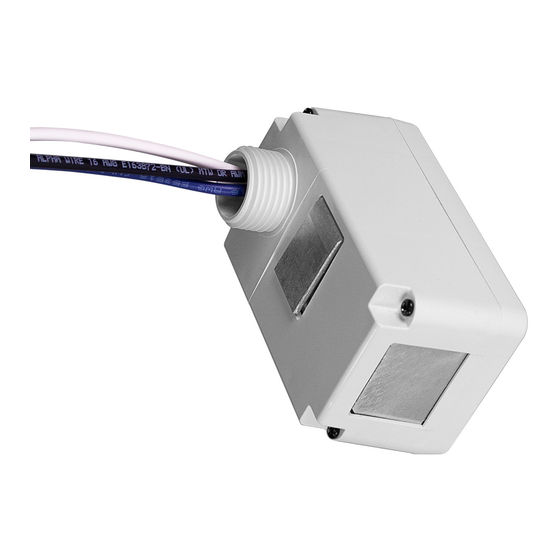
Product Description
Lumina RF Load Controllers are a component within a larger wireless control system.
They require a compatible Room Controller for enrollment and creation of networks
and ultimately to determine system functionality.
Lumina RF Devices communicate with each other, and the Room controller, via a
2.4Ghz radio on a wireless mesh network. Each line voltage powered device is a
repeater to ensure the signal get's out to all parts of the network.
Before Installation
• Install to outside or inside of junction box or outside of luminaire.
• If mounted inside, a plastic cover must be used (metal will limit the RF signal).
• LU107 uses 0-10Vdc low voltage control wires which may be installed as Class 1
or Class 2.
NOTE (LU107): 0-10V Control Wiring - Connect the violet wire to the + 0-10V line
and the gray wire to the 0-10V common using Class 1 or Class 2 wiring methods
driver label markings. Observe all requirements of any authority having jurisdiction
with respect to wire type, sleeving, isolation methods, and the like.
Installation
WARNING: TO AVOID FIRE, SHOCK, OR DEATH; TURN OFF POWER at circuit
breaker or fuse and test that power is off before wiring!
1
. Mount the Load Control device to junction box or luminaire through
1/2 in hole or knockout and secure with provided locknut.
ATTENTION: For LU04P, ensure the thermal pad is in contact with the metal
junction box. LU04P is not to be installed in enclosed junction box.
.
2
attached and there is no exposed copper.
a. LU107 Wiring Diagram
Electrical Box
Hot (Black)
Black
Line,
120/277VAC,
50/60Hz
Green
Ground
Neutral (White)
© 2020 Leviton Mfg. Co., Inc.
RF Wireless Load Control 20A Switching Relay,
RF Wireless Load Control 0-10V Dimmer
and RF Wireless Load Control 800W Dimmer
Cat. Nos. LU20S, LU107 and LU04P
INSTALLATION INSTRUCTIONS
thermal pad
LU04P
Connectors
Sleeve
Blue
Black
White
White
CAUTIONS
• Use this device with copper or copper clad wire only.
• For indoor applications only.
SAVE THESE INSTRUCTIONS.
•
b. LU20S Wiring Diagram
Hot (Black)
Line
120/277VAC,
50/60Hz.
c. LU04P Wiring Diagram
Hot (Black)
Line
120 VAC,
60Hz
Neutral (White)
3.
Restore power at circuit breaker or fuse.
4.
5.
controller.
1.
Devices must be enrolled to a room controller for system functionality.
Enrollment method/process varies by device type.
a.
LU107, LU20S
Devices are in "auto-join" mode when they power up. This means they are
seeking a network and will join a Room Controller when it allows them to join
with no specific action required by the user. Refer to your Room Controller
programming information for more details
If your LU107/LU20S does not join automatically, reset it to factory factory
defaults and try again
b.
LU04P
Violet
i.
Device enrollment must be triggered manually
ii.
Put your Room Controller in enrollment mode.
Gray
iii. Press and Hold the Toggle/Reset button for 7 seconds, then release. The
LED will blink amber. Press and release the button without holding. The
Load
LED will flash green and it will start seeking a network
0-10V
iv. When enrollment has been completed:
control
1. Successful enrollment: The locator LED will blink GREEN 3 times.
2. Failed enrollment: The locator LED will blink RED 3 times.
Blue
White
Green Ground
Neutral (White)
Black
White
Green
Ground
PK-A3314-10-00-2A
ENGLISH
Black
Load
White
Blue
Black
Load
White
PK-A3314-10-00-2A
Advertisement
Table of Contents

Related Manuals for Leviton lumina LU20S


Summary of Contents for Leviton lumina LU20S
- Page 1 When enrollment has been completed: White White control 1. Successful enrollment: The locator LED will blink GREEN 3 times. Line, 2. Failed enrollment: The locator LED will blink RED 3 times. 120/277VAC, 50/60Hz Green Ground Neutral (White) © 2020 Leviton Mfg. Co., Inc. PK-A3314-10-00-2A...
- Page 2 LIMITED 5 YEAR WARRANTY AND EXCLUSIONS Leviton warrants to the original consumer purchaser and not for the benefit of anyone else that this product at the time of its sale by Leviton is free of defects in materials and workmanship under normal and proper use for five years from the purchase date.
Need help?
Do you have a question about the lumina LU20S and is the answer not in the manual?
Questions and answers