
Subscribe to Our Youtube Channel
Related Manuals for Grundfos AquaCel AQC-D3


Summary of Contents for Grundfos AquaCel AQC-D3
- Page 1 GRUNDFOS INSTRUCTIONS AQC-D3 Measuring cell Installation and operating instructions...
- Page 2 Declaration of conformity EC Declaration of Conformity EG-Konformitätserklärung We, Grundfos, declare under our sole responsibility that the products Wir, Grundfos, erklären in alleiniger Verantwortung, dass die Produkte AquaCell AQC-D3 and the preassembled systems, to which this AquaCell AQC-D3 und die vormontierten Systeme, auf die sich diese declaration relates, are in conformity with these Council directives on the Erklärung bezieht, mit den folgenden Richtlinien des Rates zur Anglei-...
- Page 3 Декларация о соответствии EC EC uygunluk bildirgesi Мы, компания Grundfos, со всей ответственностью заявляем, что Biz, Grundfos, olarak, bu beyanda belirtilen AquaCell AQC-D3 ve önceden изделия AquaCell AQC-D3 и предварительно смонтированных систем, birleştirilmiş sistem ürünlerinin, AB Üyesi Ülkelerin kanunlarını birbirine к...
-
Page 4: Table Of Contents
2. Installation data General information Guarantee Please fill in the data below after start-up. It will Applications Note help you and your Grundfos service partner to Safety information make subsequent adjustments to the installation. Obligations of the owner Avoidance of danger Owner: Technical data 10.1 General data... -
Page 5: Installation Sketch
3. Installation sketch... -
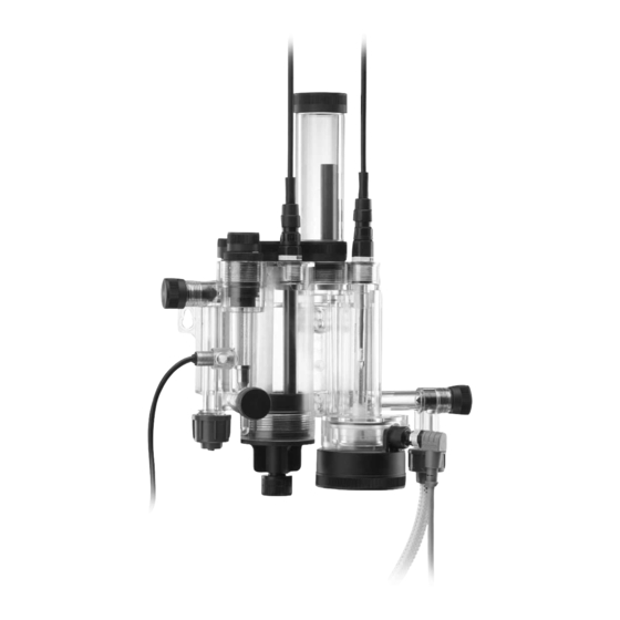
Page 6: Unit Description / Preassembled Systems
4. Unit description / preassembled systems Fig. 1 AQC-D3 potentiostatic measuring cell with ® Conex DIA / DIS measuring amplifier Fig. 2 AQC-D3 potentiostatic measuring cell with sensor interface Select Select Fig. 3 AQC-D3 potentiostatic measuring cell with DIP measuring amplifier Conex DIA-1, Conex DIA-2, Conex DIA-2Q, Conex DIS-D measuring amplifier Sensor interface for Conex DIA-1, Conex DIA-2,... -
Page 7: Identification
5. Identification 5.1 Nameplate, AquaCell Pos. Description Type designation Model Serial number Maximum pressure [bar] Product number Year and week code Country of origin Fig. 4 Nameplate, AquaCell 5.2 Type key, AquaCell Type key example AQC -D1, P AU-PCB-RCB, QS -T, G Model AquaCell Application... -
Page 8: Type Key, Preassembled System
5.3 Type key, preassembled system Example: P -AU -PCB -QS -T W -G Units for measurement and control DIA-1 Dosing Instrumentation Advanced with 1 input DIA-2 Dosing Instrumentation Advanced with 2 inputs DIA-2Q Dosing Instrumentation Advanced with 1 input + flow measurement Dosing Instrumentation Pool DIS-PR Dosing Instrumentation Standard for pH/redox measurement... -
Page 9: Unit Description / Holders For Electrodes And Sensors
6. Unit description / holders for electrodes and sensors A1/2 A1/2 Fig. 5 AQC-D3 potentiostatic measuring cell (unpressurised, hydromechanical) Pos. Component Pos. Component Shut-off spindle for sample water outlet Holders for pH single-rod electrode and redox electrode (optional) Cleaning wing A1/2 pH single-rod electrode and redox electrode (optional) Holes for fastening screws... -
Page 10: General Information
• implementation of regular maintenance. which are not handled in sufficient depth in this manual, please contact Grundfos. We will enjoy supporting you with our 9.2 Avoidance of danger comprehensive know-how in the fields of measurement and control as well as water treatment. -
Page 11: Technical Data
10. Technical data 10.2.2 Preassembled systems • Cables 10.1 General data – cable for reference electrode, pH or redox single-rod • AQC-D3: hydromechanically driven unpressurised flow electrode, 1 m, preconnected armature with open outlet for sample water. – cable for measuring electrode, 1 m, preconnected. •... -
Page 12: Dimensional Sketches / Drilling Diagram
10.4 Dimensional sketches / drilling diagram Fig. 6 Drilling diagram for AQC-D3 measuring cell Fig. 7 Drilling diagram for preassembled systems. Example with Conex DIA (wall-mounted unit) -
Page 13: Installation
11. Installation 11.4 Mounting The flow armature is fastened to the mounting plate from factory. 11.1 Transport and storage The measuring cell breaks when the screws are Transport unit carefully, do not throw, store in Caution tightened! Do not tighten the screws; only screw dry conditions between –20 and +65 °C. -
Page 14: Start-Up
12. Start-up 12.2 Water connections 12.1 Installation of electrodes and sensors Only tighten the union nut by hand. Do not use Caution any tools! 12.1.1 Reference electrode, pH and redox single-rod electrodes Observe the local pressure! The permissible 1. Unscrew the screw plugs of the holders (A, B) used for the primary water pressure is 0.3 to 3.0 bar. -
Page 15: Preparing The Electrode Cable For Connection To The Measuring Amplifier
12.3.1 Removing the floater stopper 12.4 Preparing the electrode cable for connection to the measuring amplifier 1. Close the water supply to the measuring cell. Note The preassembled systems are prewired. Warning The electrical connection should be carried out by qualified personnel! Observe the local safety regulations! Protect the cable connections and plugs against corrosion and humidity. -
Page 16: Electrical Connections
Cable from measuring electrode (D) AQC-D3 measuring cell 1. Cut the electrode cables to the desired length + approximately The cables are not preconnected. See section 105 mm for the connections. Note 12.4 Preparing the electrode cable for connection 2. Remove 105 mm of the outer insulation. to the measuring amplifier. -
Page 17: Checks Prior To Start-Up
Pos. Component 2. Take a water sample, and close the bleeding spindle (L). Brown 3. Determine the concentration of the measuring parameter White photometrically, for instance using the Grundfos DIT hand Black photometer. Blue Observe the installation and operating Caution... - Page 18 CALDATA chlorine cal cycle slope 7. Select one of the defined buffer solutions ("GRUNDFOS", 34.67 µA / ppm "DIN/NIST", the optional setting "others"), and press OK. – The menu "temperature" is then selected automatically. buffer Reading calibration data in the diagnostics menu "Service"...
-
Page 19: Operation
13. Operation 13.1.3 Influence of temperature The current generated on the electrodes depends on the 13.1 Function temperature of the sample water. Various oxidation agents are used for the disinfection of • The measured value increases by approx. 4 % per 1 °C swimming-pool water and drinking water, for instance chlorine increase. -
Page 20: Switching Off
13.2.3 Adjusting / setting the quantity of sample water 13.3.2 Long-term stop • Set the quantity of sample water with the adjustment spindle 1. Close and/or switch off the device controlled (for instance a (Q1) so that a small amount of water runs through the gas dosing unit or dosing pump). -
Page 21: Fault Finding Chart
13.5 Fault finding chart Observe the installation and operating Caution instructions of the measuring amplifier and controller! Fault Cause Remedy 1. No display. a) A disinfection or oxidation agent is missing in Check the concentration by making a reference No electricity supply to sample water. -
Page 22: Maintenance
• Replace the electrodes. – Open the bleeding spindle (L) and deaeration spindle (J), – Grundfos recommends that you replace the reference and drain the water. electrode and, if necessary, the redox or pH single-rod – Unscrew the connections to the sample water inlet (U1) and electrode after 12 months. -
Page 23: Assembling The Measuring Cell
14.3.2 Dismantling the measuring cell 14.4 Assembling the measuring cell 1. Remove the housing cylinder and ascending pipe. Only tighten screw parts by hand; do not use – Remove the housing cylinder (T), and dismantle it. Caution tools! Risk of leaking! Ensure that all O-rings are –... -
Page 24: Starting Up The Measuring Cell
This product or parts of it must be disposed of in an environmentally sound way: 1. Use appropriate waste collection services. 2. If this is not possible, contact the nearest Grundfos or Grundfos company or service workshop. Subject to alterations. - Page 27 Turkey Slatina District Unit 1, Ground floor GRUNDFOS Pumper A/S Iztochna Tangenta street no. 100 GRUNDFOS POMPA San. ve Tic. Ltd. Sti. Siu Wai Industrial Centre Strømsveien 344 BG - 1592 Sofia Gebze Organize Sanayi Bölgesi 29-33 Wing Hong Street &...
- Page 28 Thinking ahead makes it possible Innovation is the essence 96681495 1011 Repl. 96681495 0908 The name Grundfos, the Grundfos logo, and the payoff Be–Think–Innovate are registrated trademarks ECM: 1083086 owned by Grundfos Management A/S or Grundfos A/S, Denmark. All rights reserved worldwide. www.grundfos.com...
Need help?
Do you have a question about the AquaCel AQC-D3 and is the answer not in the manual?
Questions and answers