
Related Manuals for Grundfos CU 362


Summary of Contents for Grundfos CU 362
- Page 1 GRUNDFOS INSTRUCTIONS Dedicated Controls Software description Installation and operating instructions...
- Page 3 Dedicated Controls English (GB) Installation and operating instructions ............4...
-
Page 4: Table Of Contents
These installation and operating instructions apply to Grundfos 10.4 CU 362 configuration ..... . . 69 wastewater pits with a Grundfos Dedicated Controls system. The 10.5 SMSconfiguration . - Page 5 Dedicated Controls • safety instructions for Dedicated Controls • quick guide for Dedicated Controls • Dedicated Controls support CD-ROM: - this software description - additional instructions (CU 362, IO 351B, IO 11X, CIM 2XX, etc.) - functional profiles - PC Tools.
-
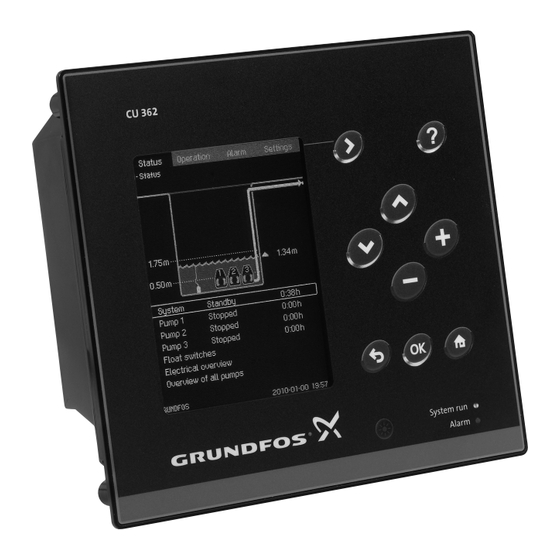
Page 6: Operating Panel For Cu 362
The display shown may differ from the actual display and save the change. on CU 362 as the display depends on the installed components and the actual configuration of the system. Green indicator light... -
Page 7: Display Layout
3.1 Display layout Scroll bar If the list of elements exceeds the display, move-up and move-down symbols appear in the scroll bar to the right. Use [Up] or [Down] to move up or down in the list. The selected element is marked with a frame. Related information 4. Main menus 3.2 Functions... -
Page 8: Main Menus
Example of "Operation" menu Example of the password dialogue box Related information 6. The "Operation" menu 4. Main menus The following sections give a short description of the four main 4.3 Alarm menus ("Status", "Operation", "Alarm" and "Settings"). This menu is used as an alarm log. The alarm log stores a record of up to 24 alarms. -
Page 9: The "Status" Menu
1" automatically changes after each pump cycle (Start level 1 - Stop level 1). If the buttons on the operating panel have not been activated for 15 minutes, CU 362 turns off the back "Status" menu light on the display. -
Page 10: System
• The red indicator light on the operating panel lights up (only in Operating Description case of alarm). parameter • "Current alarms" appears as the first line below the pit graphics. The accumulated volume of liquid removed. • The alarm relay operates. Note: Requires a flowmeter (analog or pulse Total volume •... -
Page 11: Gsm/Gprs
Status Shows whether a pump is started or stopped. Stop level Requires an analog level sensor. CU 362 (system), manually by switch (Auto/On/ When an MP 204 is installed, the following Controlled by Off) or via SCADA. parameters can be read: •... -
Page 12: Float Switch Status
"On" means that the float switch is kept up by the water. Time since Time elapsed since the mixer was last serviced service (can be reset by Grundfos Service). Example The display shows the current positions and functions of the float Time for Time until the next service is due. - Page 13 This display shows the status of the individual analog inputs. Example Analog input AI1 (CU 362) [51]: The AI1 analog input on the CU 362 (designated terminal 51) is set up as a current input. The measured value of 14.9 mA corresponds to a level and a pressure of 3.40 m.
-
Page 14: Overview Of All Pumps
The user-defined function named "Run ventilation" has been activated by the 1st source, which has been set to "Constantly high". The 2nd source has been set to "DI1 (CU 362) [10]" and is also active. This means that the ventilator is running. -
Page 15: Start And Stop Levels
CU 362 can only start and stop the pumps automatically if alarm. All pumps start, but the number of starting pumps depends the digital inputs on CU 362 and IO 351B are set to "Auto" on the number of pumps in each pump group. -
Page 16: Resetting Alarm Relays And Cancelling Interlock
Display text Description This is the lowest stop level. At this level, the first Stop level 1 pump stops. This level can be set between the dry-running level and start level 1. This is the next start level. This level must always Start level 2 be the same or higher than start level 1. -
Page 17: The "Alarm" Menu
CU 362. An alarm can cause a change of the operating mode, for example from start to stop. -
Page 18: Alarm And Warning Codes
Water-in-oil compartment high seal and oil needs replacement. Motor operating-time User-defined service interval has been reached. service interval limit CU 362 Service interval Arrange for preventive maintenance. exceeded Check cellular network connection. Check if SCADA SCADA callback fault CU 362 SCADA failed to respond phone number is correct. - Page 19 CU 362 Possible hardware fault controller. Check connection to external current transformer. Motor current sensor External analog current CU 362 AI Measure if coil has open circuit. Coil signal fault transformer fault may need replacement. Signal fault, (feedback) Signal fault on (feedback) Check sensor and connections on CUE drive.
- Page 20 Check status of add-on CIM card. Make sure CIM card SIM card fault CIM card fault card is installed correctly. Pressure sensor, CU 362 AI Sensor signal fault Check sensor signal. Replace sensor. discharge line, signal fault Flow sensor signal fault CU 362 AI Sensor signal fault Check sensor signal.
- Page 21 Distrib. pump module IO 113/MP Communication fault Check communication connections to IO 113/MP 204. communication fault Distributed I/O module Check GENI cable between CU 362 and IO 351. Check IO 351 Communication fault communication fault IO 351 GENI address. Combi event alarm Check reason why user-defined combi alarms have Combi event No.
-
Page 22: The "Settings" Menu
GENIbus number are set in this menu. The software • Adjustment of counters version is also given in this menu. • Resetting alarm log See section about general settings, CU 362. • Pump groups Submenus: • User-defined functions •... -
Page 23: Basic Functions
Changes in the inflow when pumps are running are shown if an ultrasonic sensor is selected). detected by the software and influence the calculations, but variations during an empty situation can influence the precision. Backup battery installed CU 362 can be supplied with a backup battery. - Page 24 When flow calculation is enabled, it typically takes around 10 pump Display text cycles before a flow is presented in the main screen. These pump Enter the upper measurement level used for cycles are used to learn the inflow variations, if any. Note that the Upper measurement the flow calculation.
- Page 25 • The pumps are included in the calculated volume. In this case, This emergency situation is maintained until the defective the volume of the pumps must be deducted from the calculated sensor is replaced and the alarm list is updated. volume.
- Page 26 Each float switch is linked to a function. "Saved" and "New" configurations can be seen in this display. The individual configurations are defined by Grundfos and optimised relative to the number of pumps and number of float switches. The individual configuration is shown in a table below the display.
- Page 27 8.1.4.2 Drain function, one pump and three float switches Drain function, one pump and three float switches Display: drain function, one pump and three float switches Configuration Float switch High level High level Start Start Start/stop Stop Stop Dry running Dry running 8.1.4.3 Drain function, one pump and four float switches Drain function, one pump and four float switches...
- Page 28 8.1.4.4 Drain function, two pumps and three float switches Drain function, two pumps and three float switches Display: drain function, two pumps and three float switches Configuration Float switch High level Start 2 Start 2 Start 2 Start 2 Start 1/stop Alarm Start 1 Start 1/stop...
- Page 29 8.1.4.6 Drain function, two pumps and five float switches Drain function, two pumps and five float switches Display: drain function, two pumps and five float switches Configuration Float switch High level High level Start 2 Start 2 Start 2 Start 2 Start 2 Start 2 Start 2...
-
Page 30: Advanced Functions
Status values cannot be used or system. seen on CU 362. When using SM 113 together with IO 113, IO 113 The number of IO 351B modules installed in the system must be must have communication built in to support SM 113. - Page 31 Functions that affect the daily operation of the system can be set in this menu. Path: Settings > Advanced functions Daily emptying 8.2.3 Foam draining Foam-draining parameters are set in this display. The foam-draining function can only be used if the pumps Advanced functions are suitable for dry running.
- Page 32 This ensures that the mixer operates before the pump starts. Mixer Appears only if the mixer is enabled. See section about mixer Stop level, mixer configuration. The stop level must be selected so that the mixer is submerged • Operating hours during operation.
- Page 33 Path: Settings > Advanced functions > Pump groups Resetting alarm log Pump groups 8.2.7 Pump groups This display allows the user to select pump group properties. The pumps can be split in two pump groups. The user has to define the first pump in pump group 2.
- Page 34 Example 1 Group 1: Group 2: 4 kW 15 kW 100 m 600 m Action Level [cm] Start 4 Start 3 Start 2 Start 1 Stop 4 Stop 3 Stop 2 Stop 1 Group 1 Group 2 Common settings Alternation enabled Alternation enabled Alternation enabled Max.
- Page 35 Example 2 Group 1: Group 2: Pump 1 controlled by VFD Pump 3 controlled by VFD Pump 2 Pump 4 Action Level [cm] Start 4 Start 3 Start 2 Start 1 Stop 4 Stop 3 Stop 2 Stop 1 Group 1 Group 2 Common settings Alternation enabled...
- Page 36 The source can be controlled by one of the following: It is possible to select a source from all analog and digital inputs on the CU 362 control unit and the IO 351B and IO 111 modules. • Analog input As appears from the figure below, "Timer function"...
- Page 37 This display is used to set up the 1st source of "User-def. function 2". The 1st source is set to "Internal CU 362 states". The internal state is set to "All pumps running". Path: Settings > Advanced functions > User-defined functions >...
- Page 38 AND function operator level in the wastewater pit. • AI1 (CU 362), Level, pressure. Example 2 • Water level higher than 2.5 m ("1"). The user-defined functions can also be configured by using the 1st source •...
- Page 39 The "Modules installed" submenu can be accessed from this display. • CU 362 operating panel. If flush settings have to be made, see section about flush settings. Path: Settings > Advanced functions > Variable-frequency drives If the function "Max. speed if other is running" is enabled, the pump ramps up until "Max.
- Page 40 • SCADA system at "Economy frequency", the pump runs at this frequency and • CU 362 operating panel. adjusts the frequency if the inflow changes. If flush settings have to be made, see section about flush settings. Select economy parameters: VFD interface: •...
- Page 41 PC Tool WW Controls Select economy parameters: • SCADA system • Economy level • CU 362 operating panel. • Max. economy level If flush settings have to be made, see section about flush settings. • Economy frequency VFD interface: •...
- Page 42 If the flow into the pit is larger than the flow out of the pit, the pump and the measurement are stopped. If the pump has been in operation for more than 10 minutes, it will be stopped. The specific energy measured during this period will be used.
- Page 43 SCADA system Flow calculation can be used instead of a flowmeter. • CU 362 operating panel. Specific energy is a measure of the pump efficiency measured as If flush settings have to be made, see section about flush settings. used energy [kWh] per pumped volume [m VFD interface: This display is used to show the "Specific-energy test".
- Page 44 8.2.13 Flush settings Flush settings "Flush settings" are used to prevent blocking of the pump and to minimise the risk of sedimentation in the upstream pipeline. Enable flush functions: • Reverse start • Start flushing • Run flushing • Stop flushing. See the figure below.
- Page 45 If the overflow function is selected, it must be placed on digital input The parameters that have to generate an alarm or warning must be DI3 on CU 362. The digital input is supplied from the backup battery selected. Before this function is used, a reference curve has to be making the overflow calculation possible if the power supply fails.
- Page 46 Re-activation delay is the time that has to pass when a true If the measured level in the overflow channel is 5 cm, the calculated overflow has ceased before an overflow becomes a new true overflow is 5 m /h. At 15 cm, the overflow is 15 m overflow.
-
Page 47: Communication Settings
MANAGEMENT SMART DIGITAL Grundfos Hydrogen Sulphide Solution CU 362 can handle a SMART Digital DDA dosing pump controlled The "Flush from pit" function activates after "Start interval" or "Daily via GENIbus or an Analog dosing pump controlled via digital output start time"... - Page 48 Various CIM modules are available, depending on the type of network. The CIM module must be fitted in CU 362. See the installation and operating instructions for CU 362. For configuration of the CIM module, see the installation and operating instructions and the functional profile on the CD-ROM supplied with the module.
- Page 49 8.3.11 GSM and SIM card settings 8.3.5 Ethernet 8.3.12 SCADA settings The web server of CU 362 makes it possible to connect a computer 8.3.13 Interlock settings to CU 362 via an Ethernet connection (Ethernet crossover cable). The user interface can thus be exported from CU 362 to a computer 8.3.14 GPRS settings...
- Page 50 IP configuration can be accessed. In order to use the web server, the user must know the IP address of CU 362. All network units must have a unique IP address to communicate with each other. The IP address of CU 362 from factory is 192.168.0.2.
- Page 51 8.3.6 Fieldbus addresses 8.6.6 Ethernet 8.3.6 Fieldbus addresses By installing a GENIbus module, it is possible to connect a CU 362 to an external network. The connection can be established via a GENIbus-based network or a network based on another protocol via a gateway. See section about Ethernet. For more information, contact Grundfos.
- Page 52 SCADA number A shift change can also be set in the schedule. Schedule periods The SCADA number is used for SCADA callback when CU 362 has serve practical purposes, for example, to avoid sending SMS a SCADA-callback-enabled warning or alarm.
- Page 53 8.3.9 SMS heartbeat message The heartbeat function is set in this display. A heartbeat message informs the user that CU 362 can communicate. The user can select one or more days and the time of day for sending heartbeat messages.
- Page 54 SMS heartbeat message Related information 8.3.3 CIM 250/260 (Modbus and SMS via GSM/GPRS) 8.3.4 CIM 270/280 GRM (Grundfos Remote Management) 8.3.10 SMS authentication In this display, it is possible to set incoming message authentication so that others cannot send SMS messages to the control system.
- Page 55 A test can be performed to ensure that the SCADA callback function works as intended. It can be carried out on site using CU 362 or remotely via PC Tool. CU 362 sends out a test message and the SCADA system acknowledges it.
-
Page 56: I/O Settings
• APN (Access Point Node) Example • Username The AI1 analog input on the CU 362 (designated terminal 51) is linked to the function "Level, pressure". • Password. AI1 (CU 362) [51] and AI1 (IO351B-41) [57]. The SIM card, APN address, username and password are Control unit/ supplied by the telephone company. - Page 57 "Contactor feedback, pump 1", and the contactor Example type is normally open. The AO1 analog output on IO 351B (designated terminal 18) is DI1 (CU 362) [10] and DI2 (IO351B-41) [12]. linked to the function "VFD frequency, pump 1". AO1 (IO351B-41) [18]. Control unit/...
- Page 58 Path: Settings > I/O settings > Counter inputs Example The DO1 digital output on CU 362 (designated terminal 71) is linked to "High-level alarm". DO1 (CU 362) [71] and DO1 (IO351B-41) [77].
-
Page 59: Alarm Settings
Related information 8.4.4.1 Digital outputs, output value 8.5.5 Analog fault configuration 8.5.6 Digital fault configuration 8.4.7 PTC inputs The PTC input to be set is selected in this display. As standard (one IO 351B module), there are six PTC inputs. If an extra IO 351B module is installed, 12 PTC inputs are available. The display shows each input so that its physical location can be quickly identified. - Page 60 Warnings Related information A warning does not cause the pump to stop. A warning shows that 8. The "Settings" menu the system is approaching an alarm state. 10.7 System alarms All warnings are automatically acknowledged. 10.8 Pump alarms The individual sensors must be set before this menu can 10.9 Mixer alarms be used.
- Page 61 8.5.1.1 Description of system alarms Alarm Description Overflow The alarm is displayed if an analog level sensor or a float switch registers an overflow. A high level can be set to activate an alarm relay. When the high level is reached, the system attempts to High level start both pumps.
- Page 62 Description The alarm must be set to enable the Auto/On/Off switch function. If the pump has been started or stopped by either SCADA/CU 362 operator display or "Auto/On/Off switch" for more than 5 minutes (default), this Auto/On/Off switch alarm is displayed. The user can set the delay as desired and select either warning or alarm. To prevent personal injury in the event of failure, the pump must be stopped.
- Page 63 Related information 8.2.15 Anti-blocking 8.5.3 Mixer alarms This display shows the parameters defined as mixer alarms. Select the parameter to be monitored, and set it as desired. Mixer alarms can be triggered by two fault types: • Analog fault. See section about analog fault configuration. An analog fault trips an alarm if its value lies outside a set limit.
-
Page 64: General Settings, Cu 362
The display shows the options in this menu. Display language In this menu, the CU 362 display language is selected. In connection with service, it is easy to change over to the service language using the function "Change language to the service language (English)". - Page 65 Date and time may have been changed during the setting of CU 362. There is no automatic changeover to/from daylight-saving Path: Settings > General settings, CU 362 > Units and frequency time. Path: Settings > General settings, CU 362 > Date and time...
- Page 66 Related information 8.3.6 Fieldbus addresses 8.6.8 Software status This display shows the version of the software installed in CU 362. In this display, it is possible to upgrade the software using the Grundfos CU 362 Firmware Upgrader Box. See the installation and operating instructions for the CU 362 Firmware Upgrader Box on the CD-ROM supplied with the Dedicated Controls control cabinet.
-
Page 67: Fault Finding
Cut in the main switch. Main switch defective • Replace the main switch. Motor protection tripped • Check the setting. • Contact Grundfos if the motor is defective. • Open thermistor. • Check the phase. • Contact Grundfos. Motor defective •... -
Page 68: Factory Settings
10. Factory settings 10.1 Pump This section gives an overview of the factory settings for the individual units and functions in the Dedicated Controls system. Users can thus use this overview to reconfigure the system using the factory settings. Users can also note their own settings in the overview. -
Page 69: Level
1.75 m Stop level 1 0.5 m Stop level 2 0.5 m Dry-running level 0.25 m Foam-draining level 0.15 m 10.4 CU 362 configuration Description Factory settings Own settings Units and frequency Password, Operation menu Disabled Password, Settings menu Disabled... -
Page 70: Pump Alarms
Description Factory settings Own settings Float switch Level sensor Conflicting levels Flowmeter Power meter User-defined relay output activated Hardware fault External fault Mains supply fault Battery backup (UPS) Communication fault (IO 351B) CIM module fault SCADA callback error Ethernet, no IP address from DHCP Ethernet disabled due to misuse SIM card fault User-defined sensor 1... -
Page 71: Mixer Alarms
Related information 8.5 Alarm settings 10.9 Mixer alarms Description Factory settings Own settings Contactor, mixer Time for service, mixer Max. starts/hour, mixer Related information 8.5 Alarm settings 10.10 Combi alarms Description Factory settings Own settings Combi alarm 1 Combi alarm 2 Combi alarm 3 Combi alarm 4 Related information 8.5 Alarm settings... -
Page 72: Logical Operators
11. Logical operators 11.2 OR operator The "OR" function is used when only one of the sources must be This section is intended for users who have basic knowledge of active (status high = 1) for the output signal to change its status (0 logical operators. -
Page 73: Xor Operator
11.3 XOR operator 11.4 Set/reset flip-flop The XOR function is used when both sources must be either high The "Set/reset flip-flop" function (SR-FF) is used when the 1st (1) or low (0) for the output signal to be low (0). If just one of the source has to be used to set an alarm or just to change the output sources is high (1), the output signal is high (1). -
Page 74: Reset/Set Flip-Flop
11.5 Reset/set flip-flop 11.6 Toggle flip-flop The "Reset/set flip-flop" function (RS-FF) is the same as the The "Toggle flip-flop" function (T-FF) is to be used together with a function described in the section about "Set/reset flip-flop". The only timer function. change is that the 1st source and 2nd source are interchanged. - Page 75 Tel.: +387 33 592 480 Centre Turkey Fax: +387 33 590 465 29-33 Wing Hong Street & 68 King Lam GRUNDFOS Pumper A/S GRUNDFOS POMPA San. ve Tic. Ltd. Sti. www.ba.grundfos.com Street, Cheung Sha Wan Strømsveien 344 Gebze Organize Sanayi Bölgesi E-mail: grundfos@bih.net.ba...
- Page 76 96939460 04.2021 ECM: 1294550...
Need help?
Do you have a question about the CU 362 and is the answer not in the manual?
Questions and answers