
Related Manuals for Tektronix MSO2000B Series


Summary of Contents for Tektronix MSO2000B Series
- Page 1 MSO2000B and DPO2000B Series Oscilloscopes Installation and Safety Instructions *P071307801* 071-3078-01...
- Page 3 MSO2000B and DPO2000B Series Oscilloscopes Installation and Safety Instructions www.tektronix.com 071-3078-01...
- Page 4 Copyright © Tektronix. All rights reserved. Licensed software products are owned by Tektronix or its subsidiaries or suppliers, and are protected by national copyright laws and international treaty provisions. Tektronix products are covered by U.S. and foreign patents, issued and pending. Information in this publication supersedes that in all previously published material.
-
Page 5: Table Of Contents
Table of Contents Preface ....................... Accessories and Replaceable Parts ................Documentation ....................General Safety Summary ..................Compliance Information ................... EMC Compliance....................Safety Compliance..................... Environmental Considerations ................Operating Requirements ..................Electrical Ratings ..................... Input Ratings ....................Environmental Ratings ..................Physical Specifications ..................Installation Procedure ..................... - Page 6 Table of Contents インストール手順 ..................電源投入、電源切断の手順.
-
Page 7: Preface
Simplified Chinese, and Japanese DPO2000B and MSO2000B Electronic versions of documents, 063-4472‑XX Series Oscilloscopes including the Programmer Manual Documentation CD and the Technical Reference. Tektronix OpenChoice Desktop Productivity, analysis, and 063-4402‑XX PC Communications CD documentation software. —— Calibration certificate documenting traceability to... - Page 8 For models < 100 MHz bandwidth: TPP0100 One 100 MHz, 10X passive voltage probe with 10 MΩ input resistance per channel For MSO2000B series: Digital One, 16-channel digital probe P6316 probe For MSO2000B series: Pouch that attaches to the handle...
- Page 9 Hard transit case Traveling hard case, which requires use of the soft transit HCTEK4321 case (ACD2000) DPO2000B and MSO2000B Series Service information on DPO2000B and MSO2000B series 077-0737‑XX Oscilloscopes Service manual oscilloscopes DPO2000B and MSO2000B Series Describes how to install application modules in 071-2330‑XX...
-
Page 10: Documentation
The following table lists the documentation that is available for the product and shows where you can find it: in a printed manual, on the product documentation CD-ROM, or on the Tektronix Web site at www.tektronix.com. Table 1: Product documentation... -
Page 11: General Safety Summary
General Safety Summary General Safety Summary Review the following safety precautions to avoid injury and prevent damage to this product or any products connected to it. To avoid potential hazards, use this product only as specified. Only qualified personnel should perform service procedures. While using this product, you may need to access other parts of a larger system. - Page 12 General Safety Summary Do Not Operate in Wet/Damp Conditions. Do Not Operate in an Explosive Atmosphere. Keep Product Surfaces Clean and Dry. Provide Proper Ventilation. Refer to the manual’s installation instructions for details on installing the product so it has proper ventilation. Terms in this Manual These terms may appear in this manual: WARNING.
-
Page 13: Compliance Information
IEC 61000-4-6:2003. Conducted RF immunity IEC 61000-4-11:2004. Voltage dips and interruptions immunity EN 61000-3-2:2006. AC power line harmonic emissions EN 61000-3-3:1995. Voltage changes, fluctuations, and flicker European Contact. Tektronix UK, Ltd. Western Peninsula Western Road Bracknell, RG12 1RF United Kingdom United Kingdom This product is intended for use in nonresidential areas only. - Page 14 Compliance Information Add text here to list inrush current information. Australia / New Zealand Complies with the EMC provision of the Radiocommunications Act per the following standard, in accordance with ACMA: Declaration of Conformity – EMC CISPR 11:2003. Radiated and Conducted Emissions, Group 1, Class A, in accordance with EN 61326-1:2006 and EN 61326-2-1:2006.
-
Page 15: Safety Compliance
Compliance Information Safety Compliance EC Declaration of Compliance was demonstrated to the following specification as listed in the Official Journal of the European Communities: Conformity – Low Voltage Low Voltage Directive 2006/95/EC. EN 61010-1: 2001. Safety requirements for electrical equipment for measurement control and laboratory use. - Page 16 Compliance Information Pollution Degree Pollution Degree 2 (as defined in IEC 61010-1). Note: Rated for indoor use only. Installation (Overvoltage) Terminals on this product may have different installation (overvoltage) category designations. The installation categories are: Category Descriptions Measurement Category IV. For measurements performed at the source of low-voltage installation.
-
Page 17: Environmental Considerations
(WEEE) and batteries. For information about recycling options, check the Support/Service section of the Tektronix Web site (www.tektronix.com). Mercury Notification. This product uses an LCD backlight lamp that contains mercury. Disposal may be regulated due to environmental considerations. Please contact your local authorities or, within the United States, refer to the E-cycling Central Web page (www.eiae.org) for disposal or recycling information. -
Page 18: Operating Requirements
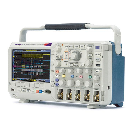
Input Voltage (between the signal and reference): 300 V CAT II Installation Category II - for measurements performed on circuits directly connected to the low-voltage installation Figure 1: MSO2000B series Figure 2: DPO2000B series MSO2000B and DPO2000B Installation and Safety Instructions... - Page 19 Operating: -10 °C to +55 °C (+14 °F to +131 °F) Nonoperating: -51 °C to +71 °C ( -60 °F to +160 °F) Pollution Degree: 2, Indoor use only Humidity: 5% to 95% RH MSO2000B Series Oscilloscope with a P6316 Threshold Accuracy: ±(100 mV + 3% of threshold) Digital Probe Threshold Range: ±20 V...
-
Page 20: Electrical Ratings
Operating Requirements Electrical Ratings Power Requirements Power connector The instrument has the following power requirements: A single-phase power source with one current-carrying conductor at or near earth-ground (the neutral conductor). NOTE. Systems with both current-carrying conductors live with respect to ground (such as phase-to-phase in multiphase systems) are not recommended as power sources. -
Page 21: Environmental Ratings
Operating Requirements Environmental Ratings Table 3: Environmental specifications Characteristic Description Temperature Operating 0 °C to + 50 °C Nonoperating -20 °C to +60 °C Humidity Operating High: 40 °C to 50 °C, 10% to 60% RH Low: 0 °C to 40 °C, 10% to 90% RH Nonoperating High: 40 °C to 60 °C, 5% to 60% RH Low: 0 °C to 40 °C, 5% to 90% RH... -
Page 22: Installation Procedure
For more information on the many probes available for use with MSO2000B and DPO2000B Series oscilloscopes, visit the Oscilloscope Probe and Accessory Selector tool on the Tektronix website. 2. TPA-BNC Adapter The TPA-BNC Adapter allows you to use Tek Probe II probe capabilities, such as providing probe power, and passing scaling and unit information to the oscilloscope. - Page 23 Other probes only pass the signal and there is no communication. 4. Digital Probe Interface (MSO2000B series only) The P6316 probe provides 16 channels of digital (on or off state) information. For more information on the many probes available for use with DPO2000B and MSO2000B series oscilloscopes, refer to www.tektronix.com.
-
Page 24: Power-On And Power-Off Procedure
Power-On and Power-Off Procedure Power-On and Power-Off Procedure This instrument operates from a single-phase power source with the neutral conductor at or near earth ground. The line conductor is fused for over-current protection. A protective ground connection through the grounding conductor in the power cord is essential for safe operation. -
Page 25: Functional Check
Power-On and Power-Off Procedure Functional Check Perform this quick functional check to verify that your oscilloscope is operating correctly. 1. Connect the oscilloscope power cable as described in Powering On the Oscilloscope. (See page 18, Power-On and Power-Off Procedure.) 2. Power on the oscilloscope. 3. -
Page 26: Compensating A Passive Voltage Probe
Power-On and Power-Off Procedure 5. Push Autoset. The screen should now display a square wave, approximately 5 V at 1 kHz. NOTE. For best performance, it is recommended that you set the Vertical scale to 1 V. If the signal appears but is misshapen, perform the procedures for compensating the probe. -
Page 27: Application Module Free Trial
Power-On and Power-Off Procedure Figure 5: Over compensated 3. If necessary, adjust your probe. Repeat as needed. Quick Tips Use the shortest possible ground lead and signal path to minimize probe-induced ringing and distortion on the measured signal. Figure 6: Signal with a short ground lead Figure 7: Signal with a long ground lead Application Module Free Trial A 30-day free trial is available for all application modules not installed in your... -
Page 28: Upgrading Firmware
Power-On and Power-Off Procedure Upgrading Firmware To upgrade the firmware of the oscilloscope: 1. Open up a Web browser and go to www.tektronix.com/software. Proceed to the software finder. Download the latest firmware for your oscilloscope on your PC. Unzip the files and copy the firmware.img file into the root folder of a USB flash drive. -
Page 29: Connecting Your Oscilloscope To A Computer
Power-On and Power-Off Procedure Connecting Your Oscilloscope to a Computer You may want to document your work for future reference. Instead of saving screen images and waveform data to a USB flash drive and generating a report later, you may want to get a copy of the image or waveform data directly from a remote PC for analysis. -
Page 30: Getting Acquainted With The Oscilloscope
Getting Acquainted with the Oscilloscope Getting Acquainted with the Oscilloscope Front-Panel Menus and Controls The front panel has buttons and controls for the functions that you use most often. Use the menu buttons to access more specialized functions. Using the Menu System To use the menu system: 1. - Page 31 Getting Acquainted with the Oscilloscope 2. Push a lower-bezel button to select a menu item. If a pop-out menu appears, turn multipurpose knob a to select the desired choice. If a pop-up menu appears, press the button again to select the desired choice. 3.
- Page 32 Getting Acquainted with the Oscilloscope Using the Menu Buttons Use the menu buttons to perform many functions in the oscilloscope. Measure. Push to perform automated measurements on waveforms or to configure cursors. Search. Push to search through an acquisition for user-defined events/criteria. Test.
- Page 33 Getting Acquainted with the Oscilloscope 11. R. Push to manage reference waveforms, including the display or removal of each reference waveform from the display. 12. M. Push to manage the math waveform, including the display or removal of the math waveform from the display. Using Other Controls These buttons and knobs control waveforms, cursors, and other data input.
- Page 34 Getting Acquainted with the Oscilloscope Zoom button. Push to activate zoom mode. Pan (outer knob). Turn to scroll the zoom window through the acquired waveform. 10. Zoom (inner knob). Turn to control the zoom factor. Turning it clockwise zooms in further. Turning it counterclockwise zooms out. 11.
- Page 35 Getting Acquainted with the Oscilloscope 17. Run/Stop. Push to start or stop acquisitions. 18. Single. Push to make a single acquisition. 19. Autoset. Push to automatically set the vertical, horizontal, and trigger controls for a usable, stable display. 20. Trigger Level. Turn to adjust the trigger level. Push Level to Set 50%.
- Page 36 30. D15 - D0. Push to display or remove the digital channels from the display, and to access the digital channel setup menu (MSO2000B series only). 31. Menu Off. Push to clear a displayed menu from the screen.
-
Page 37: Front-Panel Connectors
Getting Acquainted with the Oscilloscope Front-Panel Connectors 1. Digital Probe Connector (MSO2000B series only). 2. Channel 1, 2, (3, 4). Channel inputs with TekVPI Versatile Probe Interface. Aux In. Trigger level range is adjustable from +12.5 V to –12.5 V. -
Page 38: Rear-Panel Connectors
Getting Acquainted with the Oscilloscope 1. TekVPI external power supply connector. Use the connector for the TekVPI external power supply (Tektronix part number 119‑7465‑XX) when additional power is needed for TekVPI probes. Rear-Panel Connectors LAN. Use the LAN (Ethernet) port (RJ-45 connector) to connect the oscilloscope to a 10/100 Base-T local area network. -
Page 39: まえがき
る手順書 ついて説明します。 英語版、簡 体字中国語版、日本語版が用 意されています。 063-4472‑XX DPO2000B/MSO2000B シリー MSO/DPO4000B シリーズ・マ ズ・オシロスコープ・マニュア ニュアルの CD バージョンに ル CD は、『プログラマ・マニュアル』と 『テクニカル・リファレンス』が含 まれています。 Tektronix OpenChoice 063-4402‑XX 生産性向上、解析、および文書 Desktop PC Communications 作成用のソフトウェアです。 —— 計量標準総合センターへのト レーサビリティと、ISO9001 品 質システム登録を文書化した 校正証明書 MSO2000B and DPO2000B Installation and Safety Instructions... - Page 40 まえがき スタンダード・アクセサリ, (続き) アクセサリ 説明 当社部品番号 335-2020-00 フロント・パネル・オーバーレイ フランス語(オプション L1 型) 335-2021-00 イタリア語(オプション L2 型) 335-2022-00 ドイツ語(オプション L3 型) 335-2023-00 スペイン語(オプション L4 型) 335-2024-00 日本語(オプション L5 型) ポルトガル語(オプション L6 型) 335-2025-00 335-2026-00 簡体字中国語(オプション L7 型) 335-2027-00 繁体中国語(オプション L8 型) 335-2028-00 韓国語(オプション...
- Page 41 まえがき スタンダード・アクセサリ, (続き) アクセサリ 説明 当社部品番号 161-0348-00 電源コード 北米(オプション A0 型) 161-0343-00 汎用欧州(オプション A1 型) 161-0344-00 英国(オプション A2 型) 161-0346-00 オーストラリア(オプション A3 型) 161-0347-00 スイス(オプション A5 型) 161-0342-00 日本(オプション A6 型) 161-0341-00 中国(オプション A10 型) 161-0349-00 インド(オプション A11 型) 161-0356-00 ブラジル(オプション...
- Page 42 DPO2CONN 型 DPO2CONN 型 接続モジュール。リモート・プログラミング用のイー サネット・ポートおよびビデオ出力ポートを追加 し、オシロスコープ画面を外部モニタに表示でき るようにする。 NEX-HD2HEADER NEX-HD2HEADER Mictor コネクタから 0.1 インチのヘッダ・ピンにチャ ンネルを転送するアダプタ。 MSO/DPO2000B シリーズ・オシ 当社の Web サイト(www.tektronix.com)の ロスコープで使用する TekVPI プ Oscilloscope Probe and Accessory Selector Tool ローブ をご利用ください。 注: これらのプローブには下記の TekVPI 外部電源アダプタが必要 です。 119‑7465‑XX TekVPI 外部電源アダプタ TekVPI プローブへの外部電源...
-
Page 43: マニュアル
以 下 の 表 に 、 本 製 品 の 関 連 マ ニ ュ ア ル お よ び そ の メ デ ィ ア と 参 照 先 を 示 します。 マニュアルのメディア には、冊 子、CD-ROM 、当 社の Web サ イト (www.tektronix.com)の 3 種類があります。 表 5: 製品マニュアル... -
Page 44: 安全にご使用いただくために
安全にご使用いただくために 安全にご使用いただくために 人体への損傷を避け、本製品や本製品に接続されている製品の破損を防止 するために、安全に関する次の注意事項をよくお読みください。 安全のために、指示に従って本製品を使用してください。 資格のあるサービス担当者以外は、保守点検手順を実行しないでください。 本製品をご使用の際に、より大きな他のシステムにアクセスしなければならな い場合があります。 システムの操作に関する警告や注意事項については、他 製品のコンポーネントのマニュアルにある安全に関するセクションをお読みく ださい。 発火や人体への損傷を 適切な電源コードを使用してください: 本製品用に指定され、使用される国で 認定された電源コードのみを使用してください。 避けるには 接続と切断の手順を守ってください: プローブとテスト・リードが電圧源に接続 されている間は接続または切断しないでください。 接続と切断の手順を守ってください: 被測定回路の電源を切ってから、電流 プローブの接続あるいは切断を行ってください。 本製品を接地してください: 本製品は、電源コードのグランド線を使用して接 地します。 感電を避けるため、グランド線をアースに接続する必要があります。 本製品の入出力端子に接続する前に、本製品が正しく接地されていることを 確認してください。 すべての端子の定格を守ってください: 火災や感電の危険を避けるために、 本器のすべての定格とマーキングに従ってください。 本製品に電源を接続す る前に、定格の詳細について、製品マニュアルを参照してください。 プローブの基準リードは、グランドにのみ接続してください。 コモン端子を含むいかなる端子についても、その端子の定格の上限を超える 電位を加えないでください。 電源の切断: 電源コードの取り外しによって主電源が切り離されます。 電源 コードをさえぎらないでください。コードには常にアクセスできることが必要です。 カバーを外した状態では使用しないでください: カバーやパネルを外した状... - Page 45 安全にご使用いただくために 湿気の多いところでは使用しないでください: 爆発しやすい環境では動作させないでください: 製品の表面を清潔で乾燥した状態に保ってください: 充分な換気を確保してください: ユーザ・マニュアルの設置手順を参照し、充 分な換気を確保してください。 本マニュアル内の用語 本マニュアルでは次の用語を使用します。 警告: 人体や生命に危害をおよぼすおそれのある状態や行為を示します。 注意: 本製品やその他の接続機器に損害を与えるおそれのある状態や行為 を示します。 本製品に関する記号と用 本製品では、次の用語を使用します。 語 DANGER:直ちに人体や生命に危険をおよぼす可能性があることを示しま す。 WARNING:人体や生命に危険をおよぼす可能性があることを示します。 CAUTION:本製品を含む周辺機器に損傷を与える可能性があることを示 します。 本製品では、次の記号を使用します。 MSO2000B and DPO2000B Installation and Safety Instructions...
-
Page 46: 適合性に関する情報
IEC 61000-4-2:2001:静電気放電イミュニティ IEC 61000-4-3:2002:RF 電磁界イミュニティ IEC 61000-4-4:2004:ファスト・トランジェント/バースト・イミュニティ IEC 61000-4-5:2001:電源サージ・イミュニティ IEC 61000-4-6:2003:伝導 RF イミュニティ IEC 61000-4-11:2004:電圧低下と停電イミュニティ EN 61000-3-2:2006: AC 電源高調波エミッション EN 61000-3-3:1995: 電圧の変化、変動、およびフリッカ 欧州域内連絡先: Tektronix UK, Ltd. Western Peninsula Western Road Bracknell, RG12 1RF United Kingdom United Kingdom 本製品は住居区域以外での使用を目的としたものです。 住居区域で使用すると、電磁干 渉の原因となることがあります。 本製品をテスト対象に接続した状態では、この規格が要求するレベルを超えるエミッショ... - Page 47 適合性に関する情報 70%/25 サイクルの電圧低下および 0%/250 サイクル瞬断の各テスト・レベルにおいて、性 能基準 C を適用します(IEC 61000-4-11)。 オーストラリア/ニュー ACMA に従い、次の規格に準拠することで Radiocommunications Act の EMC 条項に適合しています。 ジ ー ラ ン ド 適 合 宣 言 -EMC CISPR 11:2003 : グ ル ー プ 1 、 ク ラ ス A 、 放 射 お よ び 伝 導 エ ミ ッ シ ョ ン (EN61326-1:2006 および...
-
Page 48: 安全性
適合性に関する情報 安全性 EC 適合宣言 - 低電圧指 『Official Journal of the European Communities』に記載の以下の基準に準拠し ます。 令 低電圧指令 2006/95/EC EN 61010-1: 2001:測定、制御および実験用途の電子装置に対する安全 基準。 米国の国家認定試験機 UL 61010-1:2004 年第 2 版:電子計測機器および試験用機器の標準規 格。 関のリスト カナダ規格 CAN/CSA-C22.2 No. 61010-1:2004:測定、制御、および実験用途の電子 装置に対する安全基準、 第 1 部。 その他の基準に対する IEC 61010-1: 2001:測定、制御、および実験用途の電子装置に対する安 全基準。... - Page 49 適合性に関する情報 汚染度 汚染度 2(IEC 61010-1 の定義による)。 注: 屋内使用のみについての評価で す。 測定カテゴリ/過電圧カ 本製品の各端子には異なる測定(過電圧)カテゴリが指定されている場合があ ります。 各測定カテゴリは次のように定義されています。 テゴリの記述 測定カテゴリ IV。低電圧電源を使用して実施する測定用。 測定カテゴリ III。建築物の屋内配線で実施する測定用。 測定カテゴリ II。低電圧電源に直接接続した回路で実施する測定用。 測定カテゴリ I。AC 電源に直接接続していない回路で実施する測定用。 過電圧カテゴリ II(IEC 61010-1 の定義による) 過電圧カテゴリ MSO2000B and DPO2000B Installation and Safety Instructions...
-
Page 50: 環境への配慮
製品を廃棄する際には適切に処理する必要があります。 有害物質の放出を 防ぎ、天然資源の使用を減らすため、本製品の部材の再利用とリサイクルの 徹底にご協力ください。 このマークは、本製品が WEEE(廃棄電気・電子機器)およびバッテ リに関する指令 2002/96/EC および 2006/66/EC に基づき、EU の 諸要件に準拠していることを示しています。 リサイクル方法について は、当社の Web サイト(www.tektronix.com)のサービス・セクションを 参照してください。 水銀に関する通知: 本製品に使用されている LCD バックライト・ランプには、 水銀が含まれています。 廃棄にあたっては、環境への配慮が必要です。 廃棄 およびリサイクルに関しては、お住まいの地域の所轄官庁にお尋ねください。 有害物質に関する規制 こ の 製 品 は Monitoring and Control ( 監 視 お よ び 制 御 ) 装 置 に 分 類 さ れ 、... -
Page 51: 動作の要件
動作の要件 動作の要件 このセクションでは、製品を安全かつ正しく使用するために把握しておくべき 仕様について説明します。 詳細については、MSO/DPO2000B シリーズ・テク ニカル・リファレンスの製品仕様の項を参照してください。 DPO2000B/MSO2000B 電源入力電圧: 100 V ~ 240 V ±10% シリーズのオシロスコー 入力電源周波数: プ 50/60 Hz(100 V ~ 240 V) 400 Hz、115 V 消費電力: 80 W(最大) 入力電圧(信号電圧と基準電圧の間): 300 V CAT II 測定カテゴリ II:低電圧電源に直接接続した回路で実施する測定用。 図 8: MSO2000B シリーズ 図... - Page 52 動作の要件 TPP0100 型 ま た は シングルエンド電圧プローブ(グランド基準): 300 V CAT II 安全基準 TPP0200 型 受 動 プ ロ ー インストレーション・カテゴリ II:低電圧電源に直接接続した回路で実施する測定用。 ブ 温度: 動作時: –10 ~ +55 ℃(+14 ~ +131 ゚F) 非動作時: –51 ~ +71 ℃(-60 ~ +160 ゚F) 汚染度: 2、ただし、屋内使用のみ 湿度:...
-
Page 53: 電気定格
動作の要件 電気定格 電源要件 電源コネクタ 本製品の電源要件は次のとおりです。 アース近傍電位の 1 本の通電導体(中性線)を持つ単相電源。 注: 2 本の通電導体が接地に対して通電状態のシステム(多相システムでの 相間など)は、電源として推奨されません。 AC 電源周波数: 50 または 60 Hz AC 電源電圧: 100 ~ 240 V 警告: 発火および感電のリスクを減らすため、主電源の電圧変動が動作電圧 レンジの 10% を超えていないことを確認してください。 ライン側のみ、過電流保護のためにヒューズが付けられています。 この内蔵 ヒューズ ヒューズはユーザによる交換を想定したものではありません。 ヒューズの交換 はしないでください。 ヒューズが飛んでいると思われる場合は、認定サービス・ センターに機器を返送して修理を受けてください。 バッテリ 本器にユーザ交換可能なバッテリはありません。 入力定格 表... -
Page 54: 環境要件
動作の要件 環境要件 表 7: 環境仕様 特性 説明 温度 動作時 0 ~ +50 ℃ 非動作時 -20 ~ +60 ℃ 湿度 動作時 高温: 40 ~ 50 ℃において、相対湿度 10 ~ 60% 低温: 0 ~ 40 ℃において、相対湿度 10 ~ 90% 非動作時 高温: 40 ~ 60 ℃において、相対湿度 5 ~ 60% 低温:... -
Page 55: インストール手順
インストール手順 インストール手順 オシロスコープとプローブは次の方法で接続できます。 プローブの接続 1. Tektronix 汎用プローブ・インタフェース(TekVPI) これらのプローブは、画面上のメニューおよびリモート設定可能な機能を 通して、オシロスコープとの双方向通信をサポートしています。 リモート・コ ントロールは、ATE(自動テスト環境)などで、システムのプローブ・パラメー タをプリセットする場合に役立ちます。 注: MSO2000B シリーズおよび DPO2000B シリーズ・オシロスコープではさまざ まなプローブを使用できます。詳細については、当社 Web サイトの Oscilloscope Probe and Accessory Selector Tool をご利用ください。 2. TPA-BNC 型\アダプタ プローブに電力を供給したり、スケーリング情報や単位情報をオシロスコー プに取り込むなど、Tek Probe II プローブの機能を使用できるようになりま す。 注: TekVPI プローブと TPA-BNC アダプタを使用するには、TekVPI 外部電... - Page 56 インストール手順 TekProbe の機能を使用して、波形信号やスケーリング情報をオシロスコー プに送るプローブもあれば、 波形信号のみを送信し、オシロスコープとの 間で通信を行わないプローブもあります。 4. デジタル・プローブ・インタフェース(MSO2000B シリーズのみ) P6316 型プローブは、16 チャンネルのデジタル(オン/オフ状態)情報を 提供します。 DPO2000B シリーズおよび MSO2000B シリーズのオシロスコープではさまざま なプローブを使用できます。詳細については www.tektronix.com を参照してく ださい。 MSO2000B and DPO2000B Installation and Safety Instructions...
-
Page 57: 電源投入、電源切断の手順
電源投入、電源切断の手順 電源投入、電源切断の手順 本製品はアース近傍電位の中性線を持つ単相電源で動作します。 ライン側 には、過電流保護のためにヒューズが付けられています。 安全な操作のため には、電源コード内の接地線を通じた保護用のグランド接続が不可欠です。 電源の投入 1. 付属の電源コードをリア・パネルの電源コネクタに接続します。 2. フロント・パネルの電源ボタンを押して、電源を投入します。 注: フロント・パネルのスタンバイ・ボタンを押しても AC 電源は切断できませ ん。 AC 電源を切断するには、リア・パネルの電源コードを抜く必要があります。 電源の切断 1. フロント・パネルの電源ボタンを押して、電源を切断します。 2. 電源を完全に切断するには、リア・パネルから電源コードを引き抜きます。 MSO2000B and DPO2000B Installation and Safety Instructions... -
Page 58: 機能チェック
電源投入、電源切断の手順 機能チェック 簡単な機能チェックを実行して、オシロスコープが正常に動作しているか確認 します。 1. 「オシロスコープの電源の投入」の説明に従って、オシロスコープの電源 ケーブルを接続します (51 ページ 「電源投入、電源切断の手順」 参照)。 2. オシロスコープの電源を投入します。 3. TPP0100 型または TPP0200 の適切なプローブ・チップとリファレンス・リー ドを、オシロスコープの PROBE COMP(プローブ補正)コネクタに接続しま す。 Default Setup を押します。 MSO2000B and DPO2000B Installation and Safety Instructions... -
Page 59: 受動電圧プローブの補正
電源投入、電源切断の手順 Autoset(オートセット)を押します。 振幅約 5 V、周波数 1 kHz の方形波 が画面に表示されます。 注: 最適なパフォーマンスを実現するため、垂直軸スケールを 1 V に設定す ることをお勧めします。 信号は表示されているのに形状がゆがんでいる場合は、プローブの補正 手順を実行します (53 ページ参照)。 信号が表示されない場合は、同じ手順を再度実行します。 それでも問題 が解消されない場合は、資格のあるサービス担当者にオシロスコープの修 理を依頼してください。 受動電圧プローブの補正 受動電圧プローブを初めて入力チャンネルに取り付ける場合は、必ずプロー ブを補正して、対応するオシロスコープの入力チャンネルに適合させるように します。 受動プローブを正しく補正するには、次の手順を実行します。 1. 次の手順に従って、機能チェックを実施します (52 ページ参照)。 2. 表示される波形の形状をチェックして、プローブが正しく補正されているか 確認します。 図 10: 適切な補正 図 11: 補正不足 MSO2000B and DPO2000B Installation and Safety Instructions... -
Page 60: アプリケーション・モジュールの無料トライアル
電源投入、電源切断の手順 図 12: 過度の補正 3. 必要に応じて、プローブを調整します。 必要なだけ調整を繰り返します。 ヒント グランド・リードと信号パスを可能な限り短くして、プローブに起因する測定信 号上のリンギングおよび歪を最小限にします。 図 13: 短いグランド・リード使用時の信号 図 14: 長いグランド・リード使用時の信号 アプリケーション・モジュールの無料トライアル オシロスコープにインストールされていないアプリケーション・モジュールは、ど れも 30 日間無料で試用できます。 トライアル期間は、初めてオシロスコープ の電源をオンにした時点から起算されます。 30 日経過後も継続使用するには、モジュールをご購入いただく必要がありま す。 トライアル期間の終了日を確認するには、フロント・パネルの Utility ボタ ンを押して、下のベゼルの Utility Page(ユーティリティ・ページ)ボタンを押し、 汎用ノブ a を使用して Config(設定)を選択し、下のベゼルの About(バージョ ン情報)ボタンを押します。 MSO2000B and DPO2000B Installation and Safety Instructions... -
Page 61: ファームウェアのアップグレード
電源投入、電源切断の手順 ファームウェアのアップグレード オシロスコープのファームウェアをアップグレードするには、次の手順を実行 します。 1. Web ブラウザを起動して、www.tektronix.com/software にアクセスし、 ソフ トウェア・ファインダを実行します。 ご使用のオシロスコープ用の最新ファー ムウェアを PC にダウンロードします。 ダウンロードしたファイルを解凍し、firmware.img ファイルを USB フラッシュ・ ドライブのルート・フォルダにコピーします。 2. オシロスコープの電源を切ります。 3. USB フラッシュ・ドライブをオシロスコープのフロント・パネルにある USB ポートに挿入します。 4. オシロスコープの電源を投入します。 アップグレード用ファームウェアが自 動的に認識され、インストールされます。 ファームウェアのインストールが開始されない場合は、同じ手順を再度実 行します。 手順を繰り返してもインストールできない場合は、別の USB フ ラッシュ・ドライブを試してください。 それでも問題が解決しない場合は、 当社営業所にご連絡ください。 注: ファームウェアのインストールが完了するまで、オシロスコープの電源を... -
Page 62: オシロスコープとコンピュータの接続
電源投入、電源切断の手順 10. About(バージョン情報)を押します。 オシロスコープにファームウェアの バージョンが表示されます。 11. バージョン番号が、新しいファームウェアの番号に一致していることを確認 します。 注: ファームウェアの更新の詳細については、MSO/DPO2000B ユーザ・マ ニュアル(PDF)を参照してください。 オシロスコープとコンピュータの接続 作業データを文書化しておけば、今後の操作で役立てることができます。 ス クリーン・イメージや波形データを USB フラッシュ・ドライブにいったん保存し、 そこからレポートを生成するという手間は不要です。イメージや波形データをリ モート PC へ直接取り込んで、解析することができます。 離れた場所にあるコ ンピュータからオシロスコープを制御することもできます。 オシロスコープをコンピュータに接続する方法は 2 つあります。1 つは VISA (Virtual Instrument Software Architecture)ドライバを経由する方法、もう 1 つ は Web 対応の e*Scope ツールを使用する方法です。 VISA を使用すると、コ ンピュータからソフトウェア・アプリケーションを介してオシロスコープと通信で... -
Page 63: オシロスコープの概要
オシロスコープの概要 オシロスコープの概要 フロント・パネル・メニューとコントロール フロント・パネルには、頻繁に使用する機能に対するボタンとコントロールが備 えられています。 メニュー・ボタンを使用すると、さらに高度な機能にアクセス できます。 メニュー・システムの使用 メニュー・システムを使用するには、次の手順を実行します。 1. フロント・パネルのメニュー・ボタンを押して、使用するメニューを表示しま す。 MSO2000B and DPO2000B Installation and Safety Instructions... - Page 64 オシロスコープの概要 2. 下のベゼル・ボタンを押して、メニュー項目を選択します。 ポップアウト・メ ニューが表示された場合は、汎用ノブ a を回して目的の項目を選択しま す。 さらにポップアップ・メニューが表示された場合は、ボタンを再度押し て、目的の項目を選択します。 3. 側面ベゼル・ボタンを押して、ベゼル・メニュー項目を選択します。 メニュー項目が複数の選択肢を含む場合は、側面ベゼル・ボタンを繰り返 し押して、選択肢を繰り返し表示させます。 ポップアウト・メニューが表示された場合は、汎用ノブ a を回して目的の項 目を選択します。 メニュー・ボタンの使用 メニュー・ボタンを使用すると、オシロスコープのさまざまな機能が実行できま す。 MSO2000B and DPO2000B Installation and Safety Instructions...
- Page 65 オシロスコープの概要 Measure(波形測定)。 このボタンを押すと、波形の自動測定を実行する か、またはカーソルが設定できます。 Search(検索)。 このボタンを押すと、取り込んだ波形を調べてユーザ定 義のイベント/基準の状況を確認することができます。 Test(テスト)。 このボタンを押すと、高度なあるいはアプリケーション固有 のテスト機能が起動します。 Acquire(波形取込)。 このボタンを押すと、アクイジション・モードを設定 してレコード長を調節することができます。 Autoset(オートセット)。 このボタンを押すと、オシロスコープの設定を自 動的にセットアップできます。 Trigger(トリガ)の Menu(メニュー)。 このボタンを押すと、トリガ設定が指 定できます。 Utility。 このボタンを押すと、言語の選択または日時の設定などのシステ ム・ユーティリティ機能が起動します。 Save/Recall Menu。 このボタンを押すと、設定、波形、スクリーン・イメー ジを内部メモリまたは USB フラッシュ・ドライブに保存することや、これらの データを呼び出すことができます。 9. チャンネル 1、2、3、または 4 の Menu(メニュー)。 これらのボタンを押す と、入力波形の垂直軸パラメータを設定したり、対応する波形をディスプレ イに表示したり、ディスプレイから消去したりできます。 10. B1 または B2。 適切なモジュール・アプリケーション・キーがある場合は、 これらのボタンを押すことで、シリアル・バスを定義または表示することがで...
- Page 66 オシロスコープの概要 さらに、B1 あるいは B2 ボタンを押すと、対応するバスを表示したり、削除 したりもできます。 11. R。 このボタンを押すと、リファレンス波形の管理(表示/非表示の切り替 えなど)ができます。 12. M。 このボタンを押すと、演算波形の管理(表示/非表示の切り替えな ど)ができます。 他のコントロールの使用 これらのボタンとノブを使用すると、波形、カーソル、および他のデータ入力を 制御できます。 1. 上側の汎用ノブ a(アクティブ時)。カーソル移動、メニュー項目のパラメー タ数値の設定、または、ポップアウト・リストの項目選択に使用します。 Fine (微調整)ボタンを押すと、粗調整と微調整を切り替えできます。 a あるいは b がアクティブな場合は、画面のアイコンにより示されます。 Cursors(カーソル)。 このボタンを一度押すと、2 つの垂直カーソルがオ ンになります。 再度押すと、2 つの垂直カーソルに加えて 2 つの水平カー ソルがオンになります。 再度押すと、カーソルはすべてオフになります。 カーソルがオンの場合は、汎用ノブを回してその位置を調節できます。 Select(選択)。 このボタンを押すと、その時々の状況に応じた機能がオ ンになります。...
- Page 67 オシロスコープの概要 Intensity(波形輝度)。 このボタンを押すと、汎用ノブ a を使用して波形 表示輝度を設定し、汎用ノブ b を使用して目盛輝度を設定できるようにな ります。 7. 下側の汎用ノブ b(アクティブ時)。カーソル移動、またはメニュー項目のパ ラメータ数値の設定に使用します。 Fine(微調整)を押すと、さらにゆっく りと調整が行えます。 Zoom(ズーム)ボタン。 このボタンを押すと、ズーム・モードがオンになりま す。 Pan(パン)(外側ノブ)。 このノブを回すと、取り込んだ波形内でズーム・ ウィンドウをスクロールできます。 10. Zoom(ズーム)(内側ノブ)。 このノブを回すと、ズーム・ファクタを制御で きます。 時計回りに回すと、さらにズーム・インします。 反時計回りに回す と、ズーム・アウトします。 11. Play-pause(実行/停止)ボタン。 このボタンを押すと、波形の自動パン を開始または停止できます。 速度および方向を制御するには、パン・ノブ を使用します。 12. ← Prev(前)。 このボタンを押すと、前の波形マークに移動します。 13. Set/Clear Mark(マークの設定/クリア)。 このボタンを押すと、波形マー クを設定または削除できます。...
- Page 68 オシロスコープの概要 15. Horizontal(水平軸)の Position(位置)。 このボタンを回すと、取り込んだ 波形に対するトリガ・ポイントの相対位置を調整できます。 Fine(微調整)を 押すと、より微細な調整が行えます。 16. Horizontal(水平軸)の Scale(スケール)。 このボタンを回すと、水平軸ス ケール(時間 /div)を調整できます。 17. Run/Stop(実行/停止)。 このボタンを押すと、アクイジションを開始また は停止できます。 18. Single(シングル)。 このボタンを押すと、1 回のアクイジションを実行しま す。 19. Autoset(オートセット)。 このボタンを押すと、適切な安定した表示のため の垂直、水平、およびトリガ・コントロールを自動で設定できます。 20. Trigger(トリガ)の Level(レベル)。 このボタンを回すと、トリガ・レベルを 調整できます。 Push Level to Set 50%(押・50%振幅)。 トリガのレベル・ノブを押すと、トリ ガ・レベルが波形の中間点に設定されます。 21. Force Trig(強制トリガ)。 このボタンを押すと、イベントをただちに強制的 にトリガします。...
- Page 69 オシロスコープの概要 22. Vertical(垂直軸)の Position(ポジション)。 このボタンを回すと、対応す る波形の垂直軸位置が調整できます。 Fine(微調整)を押すと、より微細な 調整が行えます。 23. 1、2、3、4 Menu(メニュー)。 このボタンを押すと、対応する波形の表示/ 非表示を切り替えたり、垂直軸メニューにアクセスしたりできます。 24. Vertical(垂直軸)の Scale(スケール)。 このボタンを回すと、対応する波 形の垂直軸スケール・ファクタ(V/div)を調整できます。 25. 印刷。 このボタンを押して、PictBridge 対応プリンタに印刷します。 26. 電源スイッチ。 オシロスコープの電源をオンまたはオフにします。 27. USB 2.0 ホスト・ポート。 キーボードやフラッシュ・ドライブなどの USB 周辺 機器をオシロスコープに接続します。 28. Save。 このボタンを押すと、ただちに保存操作が実行されます。 保存操 作では、Save / Recall メニューで定義された現在の保存パラメータが使用 されます。...
-
Page 70: フロント・パネル・コネクタ
オシロスコープの概要 30. D15-D0。 このボタンを押すと、ディスプレイでデジタル・チャンネルの表 示/非表示を切り替えたり、デジタル・チャンネルのセットアップ・メニュー にアクセスしたりできます(MSO2000B シリーズのみ)。 31. Menu Off。 このボタンを押すと、開いているメニューが閉じます。 32. Waveform Only。 このボタンを 1 回押すと、メニューとリードアウト情報が 画面から消え、波形またはバスのみが表示されます。このボタンをもう 1 回 押すと、前のメニューとリードアウト情報が再び表示されます。 フロント・パネル・コネクタ 1. デジタル・プローブ・コネクタ(MSO2000B シリーズのみ)。 2. チャンネル 1、2、(3、4)。 TekVPI 汎用プローブインタフェースを使用する チャンネル入力です。 Aux In。 トリガ・レベルは +12.5 V ~ –12.5 V の範囲で調整できます。 PROBE COMP(プローブ補正)。... -
Page 71: サイド・パネル・コネクタ
オシロスコープの概要 サイド・パネル・コネクタ 1. TekVPI 外部電源コネクタ。 TekVPI プローブに追加電源が必要な場合は、 このコネクタを使用して TekVPI 外部電源(当社部品番号 119‑7465‑XX)を 接続します。 リア・パネル・コネクタ LAN。 LAN(イーサネット)ポート(RJ-45 コネクタ)を使用して、10/100 Base-T ローカル・エリア・ネットワークにオシロスコープを接続します。 この ポートはオプションの接続モジュール(DPO2CONN 型)に備わっています。 ロック。 オシロスコープとオプションの接続モジュールを安全にロックしま す。 ビデオ出力。 ビデオ出力ポート(DB-15 メス型コネクタ)を使用すると、外 部モニタやプロジェクタ上にオシロスコープの画面を表示できます。 この ポートはオプションの接続モジュール(DPO2CONN 型)に備わっています。 MSO2000B and DPO2000B Installation and Safety Instructions... - Page 72 オシロスコープの概要 USB 2.0 デバイス・ポート。 USB 2.0 高速デバイス・ポートに PictBridge 対 応プリンタを接続します。また、USBTMC プロトコルを使用して、PC からオ シロスコープを直接制御することもできます。 注: 高速ホスト・コントローラに接続する場合は、USB 2.0 デバイス・ポートから ホスト・コンピュータに接続するケーブルは高速動作に対応した USB 2.0 仕様 のものを使用してください。 電源入力。 アース付きの AC 電源ケーブルを接続します。 MSO2000B and DPO2000B Installation and Safety Instructions...
- Page 73 オシロスコープの概要 MSO2000B and DPO2000B Installation and Safety Instructions...
-
Page 74: 附件和可更换部件
MSO2002B MSO2004B MSO2012B MSO2014B MSO2022B MSO2024B 有关避免人身伤害,并防止损坏本产品或与本产品连接的任何产品的 安全性预防措施 产品遵循的 EMC(电磁兼容性)、安全和环境标准 使用本产品的电压、功率和环境要求 安装步骤 开机和关机步骤 前后面板控件和连接器 附件和可更换部件 标准附件 Tektronix 部 附件 说明 件号 071-3078‑XX DPO2000B 和 MSO2000B 系列 提供安全性和符合性信息以及 示波器安装和安全说明 硬件安装说明,并以此介绍相 关安全警告。 本手册提供英 文、简体中文和日文版本。 063-4472‑XX DPO2000B 和 MSO2000B 系列 文档的电子版本,包括《编程 示波器文档光盘 手册》和《技术参考》。... - Page 75 前言 标准附件, (续) Tektronix 部 附件 说明 件号 335-2020-00 前面板面饰 法语(选件 L1) 335-2021-00 意大利语(选件 L2) 335-2022-00 德语(选件 L3) 335-2023-00 西班牙语(选件 L4) 335-2024-00 日语(选件 L5) 335-2025-00 葡萄牙语(选件 L6) 335-2026-00 简体中文(选件 L7) 335-2027-00 繁体中文(选件 L8) 335-2028-00 韩语(选件 L9) 335-2029-00 俄语(选件 L10) TPP0200 对于...
- Page 76 前言 标准附件, (续) Tektronix 部 附件 说明 件号 161-0348-00 电源线 北美(选件 A0) 161-0343-00 欧洲通用(选件 A1) 161-0344-00 英国(选件 A2) 161-0346-00 澳大利亚(选件 A3) 161-0347-00 瑞士(选件 A5) 161-0342-00 日本(选件 A6) 161-0341-00 中国(选件 A10) 161-0349-00 印度(选件 A11) 161-0356-00 巴西(选件 A12) —— 无电源线或交流适配器(选 件 A99)...
- Page 77 连接模块增加一个以太网端口用于远程控制, 并增加一个视频输出端口用于在外部监视器上 显示示波器屏幕 NEX-HD2HEADER NEX-HD2HEADER 将通道从 Mictor 连接器传输到 0.1 英寸排 针引脚的适配器 TekVPI 探 头 , 适 用 于 请访问 Tektronix 网站 (www.tektronix.com) MSO/DPO2000B 系列示波器 上的 Oscilloscope Probe and Accessory Selector Tool(示波器探头和附件选择工具) 注意: 这些探头需要使用下面列 出的 TekVPI 外部电源适配器。 119‑7465‑XX TekVPI 外部电源适配器 向 TekVPI 探头供应外部电源...
- Page 78 下 表 列 出 了 为 本 产 品 提 供 的 文 档 , 并 且 显 示 了 可 从 何 处 获 取 这 些 文 档 : 以 印刷 手 册形 式 提供 , 也可 从 产品 文 档光 盘 或 Tektronix 网 站...
-
Page 79: 常规安全概要
常规安全概要 常规安全概要 详细阅读下列安全性预防措施,以避免人身伤害,并防止损坏本产品或与 本产品连接的任何产品。 为避免可能的危险,请务必按照规定使用本产品。 只有合格人员才能执行维修程序。 使用此产品时,可能需要接触到更大系统的其他部分。 有关操作此系统 的警告和注意事项,请阅读其他组件手册的安全说明部分。 避免火灾或人身伤害 使用合适的电源线: 只使用所在国家/地区认可的本产品专用电源线。 正确连接和断开: 探头或测试导线连接到电压源时请勿插拔。 正确连接和断开: 连接电流探头或断开电流探头的连接之前请将被测电路 断电。 将产品接地: 本产品通过电源线的接地导线接地。 为避免电击,必须将 接地导线与大地相连。 在对本产品的输入端或输出端进行连接之前,请 务必将本产品正确接地。 遵循所有终端额定值: 为避免火灾或电击危险,请遵循产品上所有的额定 值和标记说明。 在连接产品之前,请先查阅产品手册,了解额定值的详 细信息。 只能将探头基准导线连接到大地。 对任何终端(包括公共终端)施加的电压不要超过该终端的最大额定值。 断开电源: 电源线可以使产品断开电源。 不要阻挡电源线;用户必须能 随时触及电源线。 切勿开盖操作: 外盖或面板打开时请勿操作本产品。 有可疑故障时不要操作: 如果怀疑本产品已损坏,请让合格的维修人员进 行检查。 远离裸露电路: 电源接通后请勿接触外露的接头和元件。 请勿在潮湿环境下操作: 请勿在易燃易爆的气体中操作: 请保持产品表面清洁干燥:... - Page 80 常规安全概要 本手册中的术语 本手册中可能使用以下术语: 警告: “警告”声明指出可能会造成人身伤害或危及生命安全的情况或 操作。 注意: “注意”声明指出可能对本产品或其他财产造成损坏的情况或操 作。 MSO2000B and DPO2000B Installation and Safety Instructions...
- Page 81 常规安全概要 产品上的符号和术语 产品上可能出现以下术语: “DANGER”(危险)表示会对人体产生直接伤害。 “WARNING”(警告)表示有可能会对人体产生伤害。 “CAUTION”(注意)表示可能会对包括本仪器在内的物品造成损害。 产品上可能出现以下符号: MSO2000B and DPO2000B Installation and Safety Instructions...
-
Page 82: 符合性信息
IEC 61000-4-5:2001。 电源线路浪涌抗扰性 IEC 61000-4-6:2003。 传导射频抗扰性 IEC 61000-4-11:2004。 电压跌落和中断抗扰性 EN 61000-3-2:2006: 交流电源线谐波辐射 EN 61000-3-3:1995: 电压变化、波动和闪变 欧洲联系方式: Tektronix UK, Ltd. Western Peninsula Western Road Bracknell, RG12 1RF United Kingdom(英国) United Kingdom(英国) 本产品仅在非居民区内使用。 在居民区内使用可能造成电磁干扰。 当该设备与测试对象连接时,可能产生超过此标准要求的辐射级别。 为确保符合上面列出的 EMC 标准,应使用高质量的屏蔽接口电缆。 在 IEC 61000-4-3 测试条件下,可包括峰-峰值不超过 4 格的光迹噪声(Trace bloom)。... - Page 83 符合性信息 澳大利亚/新西兰一致性 根据 ACMA,符合 Radiocommunications Act(无线电通信法)有关 EMC 规 声明 - EMC 定的以下标准: CISPR 11:2003 。 放 射 和 传 导 发 射 量 , 组 1 , A 类 , 依 照 EN 61326-1:2006 和 EN 61326-2-1:2006。 澳大利亚/新西兰联系方式: Baker & McKenzie Level 27, AMP Centre 50 Bridge Street Sydney NSW 2000, Australia...
-
Page 84: 安全符合性
符合性信息 安全符合性 EC 一致性声明 - 低电压 经证明符合《欧洲共同体官方公报》中所列的以下技术规范: 低电压指令 2006/95/EC。 EN 61010-1: 2001。 测量、控制和实验室用电气设备的安全性要求。 美国国家认可的测试实 UL 61010-1:2004,第 2版。 电气测量和测试设备的标准。 验室列表 加拿大认证 CAN/CSA-C22.2 No. 61010-1:2004。 测量、控制和实验室用电气设 备的安全性要求。 第 1 部分。 其他符合性 IEC 61010-1: 2001。测量、控制和实验室用电气设备的安全性要求。 设备类型 测试和测量设备。 安全级别 1 级 - 接地产品。 污染度说明 对产品周围和产品内部环境中可能出现的污染的一种量度。... - Page 85 符合性信息 测量类别 II。 用于在与低压安装直接相连的电路上进行的测量。 测量类别 I。 用于在不直接连接到市电的电路上进行的测量。 过压类别 过压类别 II(如 IEC 61010-1 中的定义) MSO2000B and DPO2000B Installation and Safety Instructions...
-
Page 86: 环境注意事项
产品报废处理 回收仪器或元件时,请遵守下面的规程: 设备回收: 生产本设备需要提取和使用自然资源。 如果对本产品的报废处 理不当,则该设备中包含的某些物质可能会对环境或人体健康有害。 为 避免将有害物质释放到环境中,并减少对自然资源的使用,建议采用适当 的方法回收本产品,以确保大部分材料可以得到恰当地重复使用或回收。 此符号表示该产品符合欧盟有关废旧电子和电气设备 (WEEE) 以及 电池的 2002/96/EC 和 2006/66/EC 号指令所规定的相关要求。 有 关回收方式的信息,请查看 Tektronix 网站 (www.tektronix.com) 上的 Support/Service(支持/服务)部分。 含汞通告: 本产品使用含汞的液晶显示屏背光灯。 出于环境因素考虑,对 该产品的处理可能受到控制。 请联络当地主管机构,如在美国境内,请 参阅电子产品循环利用中心网页 (www.eiae.org) 了解处理或回收信息。 有害物质限制 根据其分类,本产品属于监视控制设备,不在 2002/95/EC RoHS 指令规 定的范畴之内。 MSO2000B and DPO2000B Installation and Safety Instructions... -
Page 87: 操作要求
操作要求 操作要求 本 部 分 提 供 为 安 全 正 确 地 操 作 产 品 而 需 要 了 解 的 技 术 规 格 。 请 参 阅 《MSO/DPO2000B 技术参考》中的完整产品规格以了解更多信息。 DPO2000B 和 电源输入电压: 100 V 到 240 V ± 10% DPO2000B 系列示波器... - Page 88 操作要求 TPP0100 或 TPP0200 单端电压探头(以接地端为基准): 300 V CAT II 安全要求 无源探头 安装类别 II - 用于在与低电压安装直接相连的电路上进行测量。 温度: 工作状态: -10℃ 到 +55℃(+14℉ 到 +131℉) 非工作状态: -51℃ 至 +71℃(-60℉ 至 +160℉) 污染度: 2 级,仅室内使用 湿度: 5% 到 95% RH MSO2000B 系列示波器 及 P6316 数字探头 阈值精度:...
-
Page 89: 电气额定值
操作要求 电气额定值 电源要求 电源连接器 仪器具有下列电源要求: 单相电源,其中有一根载流导线接地或近地(中性导线)。 说明: 两条载流导线的接地均带电(例如多相位系统中的相间电压)的 系统不建议用作电源。 市电电源频率必须为 50 或 60 Hz。 市电电源电压必须在 100 至 240 V 范围内。 警告: 为减少起火和电击风险,请确保市电电源的电压波动不超过工作 电压范围的 10%。 保险丝 只有线路导线装有保险丝以提供过流保护。 保险丝为内置,不可由用户 更换。 请勿尝试更换保险丝。 如果您怀疑保险丝熔断了,请将该仪器送 回授权维修中心进行维修。 电池 用户不可更换仪器的电池。 输入额定值 表 10: 最大输入电压 输入 额定值 位于前面板 BNC 连接器 300 V RMS, 安装类别... -
Page 90: 环境额定值
操作要求 环境额定值 表 11: 环境技术规格 特性 说明 温度 工作状态 0℃ 到 +50℃ 非工作状态 -20℃ 到 +60℃ 湿度 工作状态 高温: 40℃ 到 50℃,10% 到 60% RH 低温: 0℃ 到 40℃,10% 到 90% RH 非工作状态 高温: 40℃ 到 60℃,5% 到 60% RH 低温:... -
Page 91: 安装步骤
1. Tektronix 通用型探头接口 (TekVPI) 这些探头通过屏幕菜单和通过可编程支持的远程方式与示波器进行双 向通信。 在希望系统预置探头参数的应用中,例如 ATE(automated test environment,自动化测试环境),远程控制十分有用。 说明: 有关适用于 MSO2000B 和 DPO2000B 系列示波器众多探头的详细 信息,请访问 Tektronix 网站上的 Oscilloscope Probe and Accessory Selector Tool(示波器探头和附件选择工具)。 2. TPA-BNC 适配器 TPA-BNC 适配器允许使用 Tek Probe II 探头功能,例如提供探头电源 以及将刻度和单位信息传递到示波器。 说明: 要使用 TekVPI 探头和 TPA-BNC ハハ配器,请将 TekVPI 外部电源适... - Page 92 安装步骤 有关适用于 DPO2000B 和 MSO2000B 系列示波器诸多探头的详细信息,请 参阅 www.tektronix.com。 MSO2000B and DPO2000B Installation and Safety Instructions...
-
Page 93: 开机和关机步骤
开机和关机步骤 开机和关机步骤 本仪器使用带接地或近地中性导线的单相电源。 线路导线上装有保险丝 进行过流保护。 通过电源线中的接地导线提供保护性接地对于安全操作 十分重要。 开机 1. 将附带的电源线接到后面板上的电源连接器上。 2. 按仪器前面板上的电源按钮,仪器将会打开。 说明: 前面板上的待机按钮不会断开市电电源。 仅产品后面的电源线可 以断开市电电源。 关机 1. 按仪器前面板上的电源按钮关闭仪器。 2. 如果要完全切断电源,请从仪器后面板断开电源线。 MSO2000B and DPO2000B Installation and Safety Instructions... -
Page 94: 功能检查
开机和关机步骤 功能检查 执行此快速功能检查以验证示波器是否正常工作。 1. 按照“打开示波器电源”中的叙述连接示波器的电源线。 ( 见第87 开机和关机步骤 页, 2. 打开示波器电源。 3. 将相应的 TPP0100 或 TPP0200 探头端部和参考引线连接到示波器的 PROBE COMP 连接器上。 4. 按 Default Setup。 5. 按“自动设置”。 屏幕上应出现一条大约 5 V,1 kHz 的方波。 MSO2000B and DPO2000B Installation and Safety Instructions... -
Page 95: 补偿无源电压探头
开机和关机步骤 说明: 为了获得最佳性能,建议将垂直刻度设为 1 V。 如果该信号出现,但已变形,请执行探头补偿过程。 ( 见第89页) 如果未出现信号,请重新运行该过程。 如果仍未解决,请将示波器交 由合格的维修人员进行维修。 补偿无源电压探头 每当首次将无源电压探头连接到任何输入通道时,请对其进行补偿以使其 与相应的示波器输入通道匹配。 要精确补偿无源探头,请执行下列操作: 1. 按以下步骤执行功能检查。 ( 见第88页) 2. 检查波形显示的形状,以确定探头是否已精确补偿。 图 17: 精确补偿 图 18: 补偿不足 图 19: 补偿过度 3. 如有必要,请调整探头。 根据需要,重复上述操作。 MSO2000B and DPO2000B Installation and Safety Instructions... -
Page 96: 应用模块免费试用
开机和关机步骤 快速提示 使用尽可能短的接地导线和信号路径,以便使测量信号的探头感应振荡和 失真减至最小。 图 20: 使用接地短导线的信号 图 21: 使用接地长导线的信号 应用模块免费试用 对于示波器上未安装的所有应用模块,提供 30 天免费试用。 试用期始 于您首次打开示波器电源的时间。 30 天以后如想继续使用该应用程序,您必须购买该模块。 要查看您的试 用期的到期日期,请按前面板 Utility 按钮,然后按下方屏幕菜单“辅 助功能页面”按钮,再使用通用旋钮 a 选择“配置”,最后按下方屏幕 菜单“版本”按钮。 MSO2000B and DPO2000B Installation and Safety Instructions... -
Page 97: 升级固件
开机和关机步骤 升级固件 要升级示波器的固件,请执行以下操作: 1. 打开 Web 浏览器访问 www.tektronix.com/software。 前进到 software finder(软件查找)部分。 将适用的示波器最新固件下载到 PC 上。 解压文件并将 firmware.img 文件复制到 USB 闪存驱动器的根文件夹 内。 2. 关闭示波器的电源。 3. 将 USB 闪存驱动器插入示波器前面板的 USB 端口。 4. 打开示波器电源。 示波器自动识别并安装更换固件。 如果示波器未安装固件,请重新运行该过程。 如果问题仍然存在,请 尝试其他型号的 USB 闪存驱动器。 最后如果需要,请联络合格的服 务人员。 说明: 在示波器完成固件安装之前,请勿关闭示波器电源或移除 USB 闪... -
Page 98: 将示波器连接到计算机
熟悉示波器 将示波器连接到计算机 您可能希望记录所做的工作以备将来参考。 不必将屏幕图像和波形数据 存储到 USB 闪存驱动器,然后再生成报告,而是直接将图像和波形数据的 副本发送到远程 PC 进行分析。 也可通过计算机控制远程位置的示波器。 将示波器与计算机连接的方法有两种,即通过 VISA(Virtual Instrument Software Architecture,虚拟仪器软件架构)驱动程序和 e*Scope Web 工具。 使用 VISA 通过软件应用程序使计算机与示波器进行通信。 使用 e*Scope 通过 Web 浏览器与示波器进行通信。 说明: 有关将示波器连接到计算机的更多信息,包括保存屏幕图像和波 形数据的说明,请参考电子版 (PDF) MSO/DPO2000B 用户手册。 熟悉示波器 前面板菜单和控制 前面板具有最常用功能的按钮和控制。 使用菜单按钮可以访问特殊的功 能。 使用菜单系统 要使用菜单系统,请执行下列操作: 1. - Page 99 熟悉示波器 2. 按下方屏幕菜单按钮选择菜单项。 如果出现弹出式菜单,旋转通用旋 钮 a 选择所需的选项。 如果出现弹出式菜单,请再次按下按钮选择 所需的选项。 3. 按某个侧屏幕按钮选择侧屏幕菜单项。 如果菜单项包含多个选项,可重复按下侧屏幕按钮可看到全部选项。 如果出现弹出式菜单,旋转通用旋钮 a 选择所需的选项。 使用菜单按钮 使用菜单按钮执行示波器中的许多功能。 测量。 按该按钮对波形执行自动测量或配置光标。 搜索。 按该按钮在捕获数据中搜索用户定义的事件/标准。 MSO2000B and DPO2000B Installation and Safety Instructions...
- Page 100 熟悉示波器 测试。 按此按钮可激活高级的或应用特定的测试功能。 采集。 按此按钮可以设置采集模式和调整记录长度。 自动设置。 按此按钮可以对示波器的设置执行自动设置。 “触发”菜单。 按此按钮可以指定触发设置。 Utility(辅助功能)。 按此按钮可以激活系统辅助功能,如选择 语言或设置日期/时间。 Save/Recall(保存/调出)菜单。 按下可保存和调出内部存储器或 USB 闪存驱动器内的设置、波形和屏幕图像。 9. 通道 1、2、3 或 4 菜单。 按下即可以设置输入波形的垂直参数,并 在显示器上显示或去除相应的波形。 10. B1 或 B2。 如果有对应的模块应用密钥,则按下即可定义和显示串 行总线。 DPO2AUTO 模块支持 CAN 和 LIN 总线。 DPO2EMBD 模块支持 C 和 SPI 总线。 DPO2COMP 模块支持 RS-232、RS-422、RS-485 和 UART 总线。...
- Page 101 熟悉示波器 使用其它控制 这些按钮和旋钮控制波形、光标和其他数据输入。 1. 激活后,旋转上方的通用旋钮 a 可以移动光标、设置菜单项的数字参 数值或从选项的弹出列表中进行选择。 按“精细”按钮可以在粗调和 细调之间进行切换。 当 a 或 b 被激活时,屏幕图标会提示。 光标。 按一次可激活两个垂直光标。 再按一次可以打开两个垂直光 标和两个水平光标。 再按一次将关闭所有光标。 光标打开时,可以旋转通用旋钮以控制其位置。 选择。 按此按钮可以激活特殊功能。 例如,当使用两个垂直光标(水平光标不可见)时,可以按此按钮链 接光标或取消光标之间的链接。 当两个垂直光标和两个水平光标都可 见时,可以按此按钮激活垂直光标或水平光标。 FilterVu。 按下可过滤信号中无用的噪声而同时仍然捕获毛刺。 精细。 按此按钮可以使用通用旋钮 a 和 b 的垂直和水平位置旋钮、 触发位置旋钮以及许多操作在粗调和细调之间进行切换 亮度。 按下可用通用旋钮 a 控制波形的显示亮度,用旋钮 b 控制 刻度亮度。...
- Page 102 熟悉示波器 缩放按钮。 按此按钮可激活缩放模式。 平移(外环旋钮)。 旋转该环可以在采集的波形上滚动缩放窗口。 10. 缩放(内环旋钮)。 旋转该旋钮可以控制缩放因子。 顺时针旋转 可以放大。 逆时针旋转可以缩小。 11. 播放/暂停按钮。 按此按钮可以开始或停止波形的自动平移。 使用 平移旋钮控制速度和方向。 12. ←(上一标记)。 按此按钮可以跳到上一波形标记。 13. 设置/清除标记。 按此按钮可以建立或删除波形标记。 14. →(下一个)。 按此按钮可以跳到下一波形标记。 15. 水平位置。 旋转此旋钮可以调整触发点相对于采集的波形的位置。 按“精细”可以进行更小调整。 16. 水平标度。 旋转此旋钮可以调整水平刻度(时间/格)。 MSO2000B and DPO2000B Installation and Safety Instructions...
- Page 103 熟悉示波器 17. 运行/停止。 按此按钮可以开始或停止采集。 18. 单次。 按此按钮进行单一采集。 19. 自动设置。 按此按钮可以自动设置垂直、水平和触发控制以进行有 用、稳定的显示。 20. 触发位置。 旋转此旋钮可以调整触发电平。 按下设为 50%。 按“触发”部分的“位置”旋钮可将触发位置设为波 形的中点。 21. 强制触发。 按此按钮可以强制执行立即触发事件。 22. 垂直位置。 旋转这些旋钮可以调整相应波形的垂直位置。 按“精 细”可以进行更小调整。 23. 1、2、3、4 菜单。 按这些按钮之一可以显示波形或删除所显示的 相应波形以及访问垂直菜单。 24. 垂直标度。 旋转此旋钮可以调整相应波形的垂直刻度因子(伏特/ 格)。 MSO2000B and DPO2000B Installation and Safety Instructions...
- Page 104 熟悉示波器 25. 打印。 按下可打印到 PictBridge 打印机。 26. 电源开关。 按下可打开或关闭示波器电源。 27. USB 2.0 主机端口。 将 USB 外设(例如键盘或闪存驱动器)插入示 波器。 28. Save(保存)。 按此按钮可以执行立即保存操作。 保存操作使用当 前保存参数,如 Save/Recall(保存/调出)菜单中所定义。 29. Default Setup(默认设置)。 按此按钮可以将示波器立即还原为默 认设置。 30. D15 - D0。 按下即在显示器上显示或删除数字通道,并访问通道设 置菜单(仅适用于 MSO2000B 系列)。 31. Menu Off(菜单关闭)。 按此按钮可以清除屏幕上显示的菜单。 32.
-
Page 105: 前面板连接器
熟悉示波器 前面板连接器 1. 数字探头连接器(仅适用于 MSO2000B 系列)。 2. 通道 1、2、(3 或 4)。 具有 TekVPI 通用探头接口的通道输入。 Aux In(辅助输入)。 触发电平范围从 +12.5 V 到 -12.5 V 可调。 PROBE COMP(探头补偿)。 用来补偿探头的方波信号源 输出电压: 0 V 至 5 V,频率: 1 kHz 5. 接地。 6. 应用模块插槽。 侧面板连接器 MSO2000B and DPO2000B Installation and Safety Instructions... -
Page 106: 后面板连接器
熟悉示波器 1. TekVPI 外部电源连接器。 如果 TekVPI 探头需要附加电源,请使用该 连接器连接 TekVPI 外部电源(Tektronix 部件号 119-7465-XX)。 后面板连接器 局域网。 使用 LAN(以太网)端口(RJ-45 连接器)将示波器连接 到 10/100 Base-T 局域网。 该端口通过可选的连接模块 (DPO2CONN) 提供。 锁。 用于保护示波器和可选的连接模块。 视频输出。 使用视频输出端口(DB-15 孔型连接器)在外部监 视器或投影仪上显示示波器的显示屏。 该端口通过可选的连接模块 (DPO2CONN) 提供。 USB 2.0 设备端口。 使用 USB 2.0 全速设备端口连接 PictBridge 兼容打印机,或者通过...
Need help?
Do you have a question about the MSO2000B Series and is the answer not in the manual?
Questions and answers