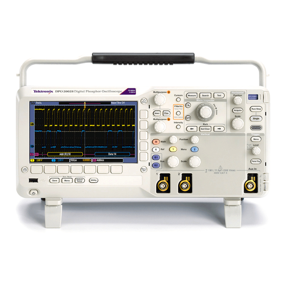
Tektronix DPO2012 Technical Reference
Dpo2000 series; mso2000 series
Hide thumbs
Also See for DPO2012:
- Programmer's manual (441 pages) ,
- User manual (272 pages) ,
- Instruction manual (132 pages)

Related Manuals for Tektronix DPO2012


Summary of Contents for Tektronix DPO2012
- Page 1 DPO2000 and MSO2000 Series Oscilloscopes Specifications and Performance Verification Technical Reference *P077009600* 077-0096-00...
- Page 3 MSO2000 Series instruments and DPO2000 Series instruments. Warning The servicing instructions are for use by qualified personnel only. To avoid personal injury, do not perform any servicing unless you are qualified to do so. Refer to all safety summaries prior to performing service. www.tektronix.com 077-0096-00...
- Page 4 Copyright © Tektronix. All rights reserved. Licensed software products are owned by Tektronix or its subsidiaries or suppliers, and are protected by national copyright laws and international treaty provisions. Tektronix products are covered by U.S. and foreign patents, issued and pending. Information in this publication supersedes that in all previously published material.
-
Page 5: Table Of Contents
Table of Contents General safety summary ..................Specifications ....................... Performance Verification ..................Upgrade the Firmware ..................Test Record ....................Performance Verification Procedures ............... DPO2000 and MSO2000 Series Specifications and Performance Verification... - Page 6 Table of Contents List of Tables Table 1: Analog channel input and vertical specifications ............. Table 2: Digital channel input specifications, MSO2000 only ..........Table 3: Horizontal and acquisition system specifications............. Table 4: Trigger specifications ..................Table 5: Display specifications..................Table 6: Input/Output port specifications ................
-
Page 7: General Safety Summary
General safety summary General safety summary Review the following safety precautions to avoid injury and prevent damage to this product or any products connected to it. To avoid potential hazards, use this product only as specified. Only qualified personnel should perform service procedures. To avoid fire or personal Use proper power cord. - Page 8 General safety summary Terms in this manual These terms may appear in this manual: WARNING. Warning statements identify conditions or practices that could result in injury or loss of life. CAUTION. Caution statements identify conditions or practices that could result in damage to this product or other property.
-
Page 9: Specifications
If the operating temperature changes by more than 10 °C (18 °F), you must perform the SPC operation again. Table 1: Analog channel input and vertical specifications Characteristic Description Number of input DPO2012, MSO2012 DPO20x4, MSO20x4 channels 2 analog, digitized simultaneously 4 analog, digitized simultaneously Input coupling DC, AC, or GND AC coupling connects a capacitor in series with the input circuitry. - Page 10 DPO2014, MSO2014, DC to ≥100 MHz 20 MHz DPO2012, MSO2012 Calculated rise time The rise time is calculated from the bandwidth of the oscilloscope. The formula accounts for the rise time contribution of the oscilloscope independent of the rise time of the signal source.
-
Page 11: Table 2: Digital Channel Input Specifications, Mso2000 Only
Specifications Table 1: Analog channel input and vertical specifications (cont.) Characteristic Description DC voltage Measurement type DC Accuracy (in volts) measurement Average of ≥ 16 waveforms ±[DC gain accuracy) × |reading - (offset - position)| accuracy, Average + Offset Accuracy] acquisition mode, Delta Volts between any two averages of ≥16 ±[DC gain accuracy ×... -
Page 12: Table 3: Horizontal And Acquisition System Specifications
DPO2024, 2 ns/div to 100 sec/div in a 1-2-4 sequence MSO2024 DPO2014, 4 ns/div to 100 sec/div MSO2014, DPO2012, MSO2012 FilterVu Peak Detect data record The minimum single pulse widths for guaranteed 50% or greater amplitude capture: pulse response Instrument... -
Page 13: Table 4: Trigger Specifications
Specifications Table 4: Trigger specifications Characteristic Description Aux In (External) trigger maximum At the BNC, between center conductor and shield, is 300 V , installation category II; derate input voltage above 4 MHz to 6 V at 200 MHz For non-sinusoidal waveforms, peak value must be less than 450 V. Excursion above 300 V should be less than 100 ms duration. - Page 14 Specifications Table 4: Trigger specifications (cont.) Characteristic Description Pulse-type runt trigger sensitivity, 0.75 division from DC to maximum bandwidth typical Aux In does not support Pulse trigger Pulse-type trigger width sensitivity, 3.5 ns when only using digital channels D0-D7 typical 4.5 ns when using any of the digital channels D8-D15 Aux In does not support Pulse trigger Logic-type triggering, minimum logic...
-
Page 15: Table 5: Display Specifications
Specifications Table 4: Trigger specifications (cont.) Characteristic Description Time range for pulse width or runt 4 ns to 8 s triggering The digital inputs do not support the runt trigger type Time accuracy for Pulse Width ±2 ns triggering Time Resolution, Logic Type 1 ns Triggers Trigger Frequency Counter... -
Page 16: Table 7: Power Source Specifications
Specifications Table 7: Power source specifications Characteristic Description Source voltage 100 V to 240 V ±10%, installation category II Source frequency (90 V to 264 V) 44 Hz to 65 Hz (100 V to 132 V) 360 Hz to 440 Hz <80 W at 85 to 275 V input Power Consumption... -
Page 17: Table 10: Mechanical Specifications
Specifications Table 10: Mechanical specifications Characteristic Description Dimensions Nominal, non-rack mount: Height: Handle down: 175 mm (6.89 in) Handle up: 180 mm (7.09 in) Depth: Handle down: 146 mm (5.74 in) Handle up: 134 mm (5.29 in) Width: 377 mm (14.85 in) from handle hub to handle hub Weight Nominal, non-rack mount: Stand-alone instrument: 3.6 kg (7.9 lbs) - Page 18 Specifications DPO2000 and MSO2000 Series Specifications and Performance Verification...
-
Page 19: Performance Verification
1 ms period, ±1 ppm accuracy, rise time < 25 ns One 50 Ω BNC cable Male-to-male connectors Tektronix part number 012-0057-01 Tektronix part number 011-0049-02 One 50 Ω feedthrough termination BNC male and BNC female connectors For MSO2000 Series only:... -
Page 20: Upgrade The Firmware
For the best functionality, you can upgrade the oscilloscope firmware. To upgrade the firmware, follow these steps: 1. Open up a Web browser and go to www.tektronix.com/software. Use the Software and Firmware Finder to locate the most recent firmware upgrade. -
Page 21: Test Record
Performance Verification Test Record Model Serial Procedure performed by Date Test Passed Failed Self Test Signal Path Compensation (SPC) Performance Checks DC Balance Channel Coupling Low limit Test result High limit Channel 1 -21 mV 21 mV -21 mV 21 mV Channel 2 -21 mV 21 mV... - Page 22 Performance Verification Bandwidth Channel Low limit Test result High limit — — Channel 1 2.12 V — — 2.12 V Channel 2 — — 2.12 V Channel 3 — — Channel 4 2.12 V Channels 3 and 4 are only on four channel oscilloscopes Vertical Position Range Trace Channel...
- Page 23 Performance Verification Digital Threshold Accuracy, MSO2000 series only Digital Test result channel Threshold Low limit High limit sAvg -0.1 V 0.1 V 3.78 V 4.22 V -0.1 V 0.1 V 3.78 V 4.22 V -0.1 V 0.1 V 3.78 V 4.22 V -0.1 V 0.1 V...
-
Page 24: Performance Verification Procedures
If your oscilloscope firmware version is v1.02, it should be updated before performing the Performance Verification procedures. Download the latest firmware from www.tektronix.com/software. The following three conditions must be met prior to performing these procedures: 1. The oscilloscope must have been operating continuously for twenty (20) minutes in an environment that meets the operating range specifications for... - Page 25 Performance Verification 5. Push the Self Test lower-bezel button. The Loop X Times side-bezel menu will be set to Loop 1 Times. DPO2000 and MSO2000 Series Specifications and Performance Verification...
- Page 26 Performance Verification 6. Push the OK Run Self Test side-bezel button. 7. Wait while the self test runs. When the self test completes, a dialog box displays the results of the self test. 8. Push the Menu Off button to clear the dialog box and Self Test menu. Signal Path Compensation This process corrects for DC inaccuracies caused by temperature variations and/or long term drift.
- Page 27 Performance Verification 4. Push the Source lower-bezel button. 5. Select the AC Line trigger source with Multipurpose knob a. You do not need to connect an external signal to the oscilloscope for this DC Balance test. 6. Push the front-panel Acquire button. 7.
- Page 28 Performance Verification Check DC Gain Accuracy This test checks the DC Gain Accuracy of each channel. 1. Push the front-panel Default Setup button to set the instrument to the factory default settings. 2. Push the front-panel Horizontal Acquire button, then push the bottom-bezel Average button, and then push the side-bezel Average button, to turn averaging on.
-
Page 29: Table 11: Dc Gain Accuracy Worksheet
Performance Verification d. Calculate V – V , and then enter V in the test record. As an diff diff example, on the 5 mV/div setting, if V is 17.4 mV and V is -17.2 mV, then V is 34.6 mV. diff e. - Page 30 Model Frequency DPO2024, MSO2024 200 MHz DPO2012, DPO2014, MSO2012, MSO2014 100 MHz 18. Use the Horizontal Scale knob to set the oscilloscope to 10 ns/div. 19. Check that the peak-to-peak measurement is ≥2.12 V. Enter this measurement in the test record.
- Page 31 Performance Verification Check Vertical Position This test checks the offset range for each channel. Range 1. Connect the oscilloscope to a DC voltage source to run this test. If using the Fluke calibrator as the DC voltage source, connect the calibrator head to the oscilloscope channel to test.
- Page 32 Performance Verification 17. Push the Set to 0V side-bezel button. 18. Use the Vertical Scale knob to set the oscilloscope to 5 V/div. 19. Use the Vertical Position knob to place the trace at the bottom of the display (-4 divisions). 20.
- Page 33 Performance Verification Check Sample Rate and This test checks the sample rate and horizontal position time accuracy (time base). Horizontal Position Time 1. Connect the output of the time mark generator to the oscilloscope Accuracy channel 1 input using a 50 Ω cable and 50 Ω feedthrough terminator. 2.
- Page 34 Performance Verification 14. If necessary, turn the Horizontal Position knob to set the delay to exactly 1.0000 ms. 15. Compare the rising edge of the marker with the center horizontal graticule line. The rising edge should cross the 0 V center within ±2.5 divisions (±25 ns) of the center graticule line.
- Page 35 Performance Verification 8. Push the side-bezel D7 - D0 button. Before you change the threshold value, push the Fine front-panel button to turn off the fine adjustment and make adjusting the value quicker. 9. Use Multipurpose knob a to set the D7-D0 threshold level to 0 V. 10.
- Page 36 Performance Verification Compare the test result to the limits. If the result is between the limits, continue with the procedure to test the channel at the +4 V threshold value. 19. The remaining part of this procedure is for the +4 V threshold test. Push the front-panel D15-D0 button.
Need help?
Do you have a question about the DPO2012 and is the answer not in the manual?
Questions and answers