Table of Contents
Advertisement
Quick Links
Instruction Manual
D103553X012
Fisherr Large ET and ED Valves
NPS 12 through 16 and NPS 30
Contents
. . . . . . . . . . . . . . . . . . . . . . . . . . . . . . . . .
. . . . . . . . . . . . . . . . . . . . . . . . . . . . .
. . . . . . . . . . . . . . . . . . . . . . . . . . . . . . . . .
. . . . . . . . . . . . . . . . . . . . . . . . . . . . . . .
. . . . . . . . . . . . . . . . . . . . . . . . . . . . . . . . . .
. . . . . . . . . . . . . . . . . . . . . . . . . . . . . . . .
. . . . . . . . . . . . . . . . . . . . . . . . . .
. . . . . . . . . . . . . . . . . . . . . . . . .
. . . . . . . . . . . . . . . . . . . . . . . . . .
. . . . . . . . . . . . . . . . . . . . . . . . . .
. . . . . . . . . . . . . . . . . . . . . . . . . . . . . . .
. . . . . . . . . . . . . . . . . . . . . . . . . . . . . . . . . . .
Introduction
Scope of Manual
This instruction manual includes installation and maintenance information for NPS 12 through 16 and NPS 30 CL150
through 600 Fisher ET and ED valves.
Refer to separate manuals for instructions covering the actuator and accessories.
Do not install, operate, or maintain an ET or ED valve without being fully trained and qualified in valve, actuator, and
accessory installation, operation, and maintenance. To avoid personal injury or property damage, it is important to
carefully read, understand, and follow all the contents of this manual, including all safety cautions and warnings. If you
have any questions about these instructions, contact your Emerson Process Management sales office before
proceeding.
www.Fisher.com
. . . . . . . . . . . . . . . . . . . . . . . .
. . . . . . . . . . . . . . . . .
. . . . . . . . . . . . . . . . . .
. . . . . . . . . . . . . . . . . . . . . . .
. . . . . . . . . . . . . .
. . . . . . . .
. . . .
. . . . . . . . . . . . . .
. . . . . . . . . . . . . .
. . . . . . . . . . . . . .
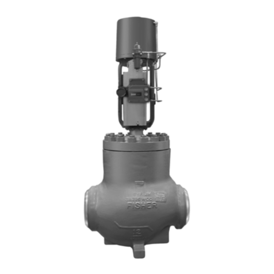
Figure 1. Fisher NPS 12 Valve with Piston Actuator
and FIELDVUE™ DVC6200 Digital Valve Controller
1
1
3
4
4
6
7
7
9
12
12
13
13
15
19
21
21
23
23
23
24
25
Large ET and ED Valves
December 2011
Advertisement
Table of Contents

Related Manuals for Emerson Fisher Large ET


Summary of Contents for Emerson Fisher Large ET
-
Page 1: Table Of Contents
To avoid personal injury or property damage, it is important to carefully read, understand, and follow all the contents of this manual, including all safety cautions and warnings. If you have any questions about these instructions, contact your Emerson Process Management sales office before proceeding. - Page 2 120 that are compatible with the ASME B16.34 valve body rating Port Diameters For other end connections, contact your Emerson NPS 12, 14, and 16 Trim: 279.4 mm (11.00 inches) Process Management sales office for details and 254 mm (10.00 inches) NPS 30 Trim: 609.6 mm (24.00 inches)
-
Page 3: Description
Maximum Pressure Drops some constructions. Contact your Emerson Process As shown in this bulletin. Also see Bulletin Management sales office for details 51.1:Large_ET_ED, Fisher Large ET and ED Valves NPS 12 through 16 Flow Direction Standard and Cavitrol III Cages: Down... -
Page 4: Specifications
Instruction Manual Large ET and ED Valves December 2011 D103553X012 Figure 2. Cutaway Detail of Fisher WhisperFlo Trim, Valve Body Typical W6825-1 Fisher WhisperFlo trim represents state of the art solutions for applications that demand ultimate aerodynamic noise attenuation. Control valves with WhisperFlo cages (figure 2) provide additional aerodynamic noise attenuation in very demanding vapor or gas applications with high-pressure drops. - Page 5 Shrunk-fit pieces and threaded connections might also loosen. If post weld heat treating is to be performed, all trim parts should be removed. Contact your Emerson Process Management sales office for additional information.
-
Page 6: Maintenance
Instruction Manual Large ET and ED Valves December 2011 D103553X012 6. If continuous operation of the plant is required during inspection or maintenance of the valve, install a three-valve bypass around the control valve assembly. 7. If the actuator and valve are shipped separately, refer to the actuator mounting procedure in the appropriate actuator instruction manual. -
Page 7: Packing Lubrication
Instruction Manual Large ET and ED Valves D103553X012 December 2011 Figure 3. Lubricator and Lubricator/Isolating Valve LUBRICATOR 10A9421-A AJ5428-D LUBRICATOR/ISOLATING VALVE A0832-2 Note Whenever a gasket seal is disturbed by removing or shifting gasketed parts, a new gasket should be installed upon reassembly. This is necessary to ensure a good gasket seal because the used gasket might not seal properly. - Page 8 Instruction Manual Large ET and ED Valves December 2011 D103553X012 Figure 4. Typical Packing UPPER WIPER UPPER WIPER (KEY 12) (KEY 12) PACKING PACKING FOLLOWER FOLLOWER (KEY 13) (KEY 13) FEMALE FEMALE ADAPTOR ADAPTOR PACKING RING MALE MALE WASHER ADAPTOR ADAPTOR SPACER (KEY 8) (KEY 10)
-
Page 9: Replacing Packing
Instruction Manual Large ET and ED Valves D103553X012 December 2011 is possible that the leakage is caused by nicks or scratches around the packing box wall. If performing any of the following procedures, inspect the valve stem and packing box wall for nicks and scratches. Figure 4. - Page 10 Instruction Manual Large ET and ED Valves December 2011 D103553X012 Figure 5. Typical Globe Valve Bonnet CU4317 Note The following step also provides additional assurance that the valve body fluid pressure has been relieved. 4. Hex nuts (key 16, figures 7 or 8) attach the bonnet to the valve body. Loosen these nuts or cap screws approximately 3 mm (1/8 inch).
- Page 11 1290 1. For B7, B7M, B16, and 660 bolting materials. For other materials, contact your Emerson Process Management sales office for torque values. 8. Install screws or bolts into the tapped holes in the top of the cage assembly (key 3), and carefully lift it out of the valve body.
-
Page 12: Trim Maintenance
Instruction Manual Large ET and ED Valves December 2011 D103553X012 18. For spring-loaded PTFE V-ring packing, tighten the packing flange nuts until the shoulder on the packing follower (key 13, figure 5) contacts the bonnet. For graphite packing, tighten the packing flange nuts to the maximum recommended torque shown in table 3. Then, loosen the packing flange nuts and retighten them to the recommended minimum torque shown in table 3. -
Page 13: Lapping Seating Surfaces
Instruction Manual Large ET and ED Valves D103553X012 December 2011 For ED valves (figure 8), unscrew the seat ring cap screws (key 49). Install screws or bolts into the tapped holes in the top of the seat ring (key 9) and carefully lift it out of the valve body. Remove the gasket (key 13). 7. - Page 14 Instruction Manual Large ET and ED Valves December 2011 D103553X012 Figure 6. Seal Ring and Piston Ring Details CAGE CAGE (KEY 3) (KEY 3) VALVE VALVE PLUG PLUG (KEY 2) (KEY 2) SEAL PISTON RING RINGS (KEY 28) (KEY 28) PISTON RINGS FOR SEAL RING FOR ED VALVES...
-
Page 15: Trim Replacement
Instruction Manual Large ET and ED Valves D103553X012 December 2011 CAUTION Never reuse an old stem (key 7) with a new valve plug. Using an old stem with a new plug requires drilling a new pin hole in the stem. This weakens the stem and may cause it to fail in service. However, a used valve plug may be reused with a new stem. - Page 16 Instruction Manual Large ET and ED Valves December 2011 D103553X012 3. Slide the valve plug (key 2) and stem assembly into the cage. For valves with a seal ring, make sure the valve plug seal ring (key 28) is evenly engaged in the entrance chamfer at the top of the cage or cage assembly to avoid damaging the ring.
- Page 17 Instruction Manual Large ET and ED Valves D103553X012 December 2011 Figure 8. Typical Fisher ED Valve APPLY LUB B2411...
- Page 18 Instruction Manual Large ET and ED Valves December 2011 D103553X012 Figure 9. Typical Fisher ET Valve with HTS1 Option...
-
Page 19: Retrofit: Installing Bore Seal Trim
Additional actuator thrust is required for a valve with Bore Seal trim. When installing Bore Seal trim in an existing valve, contact your Emerson Process Management sales office for assistance in determining new actuator thrust requirements. Assemble the new valve plug/retainer assembly (with Bore Seal plug seal) using the following instructions:... - Page 20 GE17914X012 11.00 1. For sizes,contact your Emerson Process Management sales office. 5. Apply a suitable high-temperature lubricant to the threads on the plug. Then, place the Bore Seal retainer onto the plug and tighten the retainer using an appropriate tool such as a strap wrench. For flow down constructions, skip to step 7.
-
Page 21: Replacement Of Installed Bore Seal Trim
Instruction Manual Large ET and ED Valves D103553X012 December 2011 8. Install the new plug/retainer assembly with Bore Seal on the new stem following the appropriate instructions in the Trim Replacement section of this manual. 9. Install piston rings by following instructions in the Trim Replacement section of this manual. 10. - Page 22 Instruction Manual Large ET and ED Valves December 2011 D103553X012 Figure 12. Stake the Threads of the Bore Seal Retainer DEFORM THREAD TO STAKE Bore Seal RETAINER PISTON RING RETAINER Bore Seal METAL PLUG SEAL VALVE PLUG FLOW DOWN A6779 CAUTION Do not remove the valve stem from the plug/retainer assembly unless you are planning to replace the valve stem.
-
Page 23: Lapping Metal Seats (Bore Seal Constructions)
Instruction Manual Large ET and ED Valves D103553X012 December 2011 Figure 13. Lower (Valve Plug to Seat Ring) and Upper (Bore Seal to Cage) Seating Surfaces RETAINER PISTON RING CAGE SEATING AREA PLUG BORE SEAL UPPER SEATING SURFACE CAGE PLUG SEAT RING LOWER SEATING SURFACE... -
Page 24: Parts Ordering
Refer to the serial number when contacting your Emerson Process Management sales office for technical assistance. When ordering replacement parts, refer to the serial number and to the key number and part name from the following list. -
Page 25: Parts List
Special Washer, stainless steel (single Note packing only) 1H995936042 Part numbers are shown for recommended spares only. For part PTFE/Composition Packing numbers not shown, contact your Emerson Process Management sales Packing Ring, PTFE/composition (8 req'd) 1D7520X0012 office. Lantern Ring, stainless steel 0W087135072... - Page 26 Instruction Manual Large ET and ED Valves December 2011 D103553X012 Figure 14. Typical Fisher WhisperFlo Trims BONNET CAGE RETAINER WhisperFlo CAGE CAP SCREW SEAT RING...
- Page 27 Instruction Manual Large ET and ED Valves D103553X012 December 2011...
- Page 28 Responsibility for proper selection, use, and maintenance of any product remains solely with the purchaser and end user. Fisher, FIELDVUE, Cavitrol, WhisperFlo, Whisper Trim, and ENVIRO-SEAL are marks owned by one of the companies in the Emerson Process Management business division of Emerson Electric Co.
Need help?
Do you have a question about the Fisher Large ET and is the answer not in the manual?
Questions and answers