Table of Contents
Advertisement
Advertisement
Table of Contents

Related Manuals for Arkel KM-10


Summary of Contents for Arkel KM-10
- Page 1 KM-10 User Manual V1.10 KM-10 ELEVATOR DOOR CONTROLLER USER MANUAL...
- Page 2 This document has been created to be a guide for Arkel customers. Reproduction, transfer, distribution or storage of part or all of the contents in this document in any form without the prior written permission of Arkel is prohibited. Arkel reserves the right to make changes and improvements to any of the products described in this document without prior notice.
-
Page 3: Table Of Contents
............................10 EYPAD ONİTORİNG PERATİON 9.3. & O ......................... 10 CREENS 10. ACCESSING MENU ................................. 11 11. PARAMETERS ................................. 13 12. PARAMETER SETTING VIA KM-10 KEYPAD ......................13 12.1. ETTİNGS ..........................13 ENERAL ARAMETER 12.2. PENİNG ETTİNGS ............................15 12.3. -
Page 4: Introduction
KM-10 User Manual V1.10 Introduction KM-10 controller is an “intelligent” door control board designed for automatic telescopic lift doors with 24VDC reduction gear motor. It provides advance features for high comfort, high dynamic performance and flexible usage. • KM-10 provides complete hold of the motor with its 4-region motor control and high-resolution encoder input hardware. -
Page 5: Technical Specifications
KM-10 User Manual V1.10 Technical Specifications Input supply: 20VAC±10% Supply voltage: 10W (Control circuit) + Motor power Max. Power consumption: Short-circuit protection (8A) Supply protection: Motor outputs: 24VDC Motor voltage: Max. 200W (8A) Motor output power: 4-region motor control Motor control type:... -
Page 6: Overview Of Km-10 Door Controller
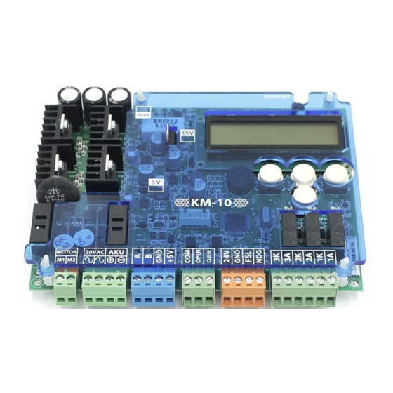
KM-10 User Manual V1.10 Overview of KM-10 Door Controller Figure 1 KM-10 layout LCD Contrast adjustment Assembly holes 2x16 character display Motor output terminals 4-button keypad AC power supply and emergency supply terminals Motor driving transistors with coolers Encoder input terminals... -
Page 7: Description Of Led's
KM-10 User Manual V1.10 Description of Led’s Figure 2 Description of Leds Supply indicators Status Description +5V supply is active (Supply for microcontroller and encoder) +5V supply is inactive +15V supply is active (Supply for motor drive circuit) ... -
Page 8: Connection Diagram
Photocell signal input (or Motor PTC input) (Inputs are activated with 24VDC internal supply) *If FSL input is used as motor PTC the signal must be active during normal operation. If signal is interrupted KM-10 gives PTC error. Inputs from lift control system Can be supplied with internal or external 24Vdc. -
Page 9: Control Inputs Connection
Note: The inputs are dual channel opto-coupled. Positive or negative common is selectable. In the sample figures above only connection with negative common is shown. Onboard Keypad & Display 9.1. Keypad and Lcd Display KM-10 Keypad provides 2-line 16-character LCD module and 4-button keypad. 2-line 16-character LCD module Figure 6 KM-10 display and keypad user interface... -
Page 10: Keypad Functions
KM-10 Keypad display shows a main screen (Door status), control signal screen (Input signals) and manual operation screen. Figure 7 Screen Flows When the power is first applied, KM-10 Keypad display shows the software version. ARKEL KM-10 V:x.x Figure 8 Screen Flows Then the main screen is shown. -
Page 11: Accessing Menu
KM-10 door controller provides a parameter menu which has access levels for security, user/customer needs and easy adjustment. These access levels are limited level, basic level and manufacture level. Accessing menu with the keypad on board is limited level. KM-10 Keypad is required for accessing menu in a basic level or in a manufacture level. - Page 12 KM-10 User Manual V1.10 RESET Basic Level Manufacturer Level Main Menu Main Menu Language Language Speed setting Speed setting Default speed Default speed settings settings Personel speed Personel speed settings settings Other basic Manufacturer settings basic settings Other basic settings...
-
Page 13: Parameters
SPEED CONT. KP Manufacture SPEED CONT. KI Manufacture GEAR RATIO 1 Manufacture GEAR RATIO 2 Manufacture W. CIRCUMFERENCE Manufacture COUNT CLEAR CODE Manufacture Parameter Setting via KM-10 Keypad 12.1. General Parameter Settings LANGUAGE Menu language TURKCE Turkish ENGLISH English Ελληνικά Greek русский... - Page 14 FSL input can be programmed to monitor motor PTC. DISABLED FSL input is used to monitor photocell. FSL input is used to monitor motor PTC. If signal on the FSL input is interrupted KM-10 ENABLED gives PTC error. LEARNING SPEED Door auto-learning speed during the measurement of the door travel length.
-
Page 15: Door Opening Settings
KM-10 User Manual V1.10 12.2. Door Opening Settings Adjust door opening settings by referring to Figure-14. OPENING SPEED The maximum opening speed. Opening slow speed when door reaches to the opening rubber stopper. OPENING SLOW SPD The opening distance while door accelerates. (From slow speed to opening speed) and... -
Page 16: Emergency Operation
KM-10 User Manual V1.10 GEAR RATIO 1 GEAR RATIO 2 W. CIRCUMFERENCE ENCODER PULSE Figure 17 Motor settings Samples to determine motor gear ratio from motor name plate are shown below: Sample motor name plate 1: Sample motor name plate 2:... -
Page 17: Status Messages
Door is closing. The door closing speed and door position data is shown on display. Error Messages The error messages of KM-10 door controller which are shown either on KM-10 Keypad display or onboard digital display are listed below: KM-10 Keypad LCD module... -
Page 18: Dimensions
KM-10 User Manual V1.10 DOOR OFTEN DETECTS OBSTACLE • Check that door has no mechanical defect. • Check that obstruction pressure is not too low. • Check that encoder is not faulty. • Check that Ac power supply is not too low DOOR PANELS ARE VIBRATING •...
Need help?
Do you have a question about the KM-10 and is the answer not in the manual?
Questions and answers