
Related Manuals for Clarke CGW1


Summary of Contents for Clarke CGW1
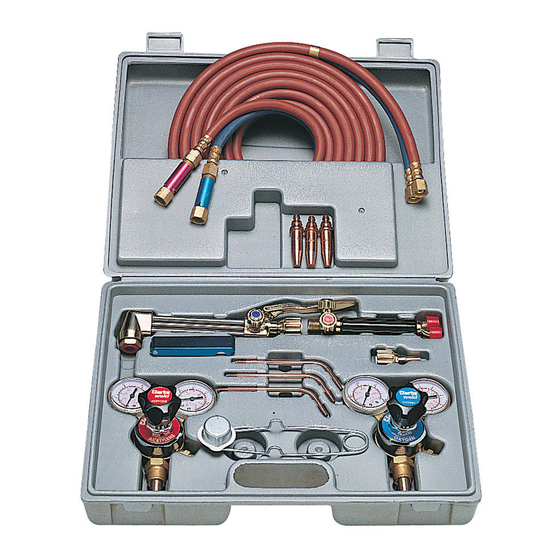
- Page 1 WELDING KIT MODEL CGW1 PART NO: 6000670 USER INSTRUCTIONS ORIGINAL INSTRUCTIONS GC0917 iSSUE 2...
-
Page 2: General Safety Precautions
INTRODUCTION Thank you for purchasing this CLARKE Welding Kit. Before attempting to use this product, please read this manual thoroughly and follow the instructions carefully. In doing so you will ensure the safety of yourself and that of others around you, and you can look forward to your purchase giving you long and satisfactory service. -
Page 3: Additional Safety Precautions
4. When welding, users and bystanders must ALWAYS use a protective headshield fitted with the correct shade of lens. Failure to do so can cause serious damage to your eyes. 5. ALWAYS learn the product applications, limitations and the specific potential hazards peculiar to it. - Page 4 ALWAYS ensure the non return valves/flash back arrestors supplied are fitted to both lines. ALWAYS use recommended pressure settings. Improper settings are wasteful. Extreme pressure build up in regulators is a warning to have them checked and repaired. ALWAYS “crack” the oxygen cylinder valve before installing the regulator, this is carried out by briefly opening the valve and allowing the escaping oxygen to clear away any dust which could damage the regulator.
-
Page 5: Setting Up Instructions
SETTING UP INSTRUCTIONS WARNING: ENSURE THERE ARE NO NAKED FLAMES OR SPARKS WHICH COULD IGNITE WHEN PRIMING OR PURGING THE HOSES ETC. ENSURE A FIRE EXTINGUISHER IS ALWAYS AT HAND IN CASE OF ACCIDENTS. ATTACHING THE REGULATORS (FIG 1) Open the oxygen cylinder valve (arrowed) briefly to blow out any dust etc, ensure the valve is fully closed before continuing. - Page 6 ATTACHING THE TORCH (FIG 3) Attach the acetylene hose complete with flame arrestor (Red) to the torch inlet valve marked ‘GAS’ and the oxygen hose complete with flame arrestor (Blue) to the torch inlet valve marked ‘OX’. Tighten both connectors using a 19mm open ended spanner, DO NOT overtighten.
- Page 7 INSTALLING THE CUTTING/WELDING NOZZLE (FIG 6, 7 & 8) WELDING Remove the cutting torch if fitted, attach the welding nozzle adapter to the welding torch/handle, tightening hand tight only. Select the required welding nozzle and screw into the adapter. To prevent the adaptor from turning, hold in position with a 11mm open ended spanner.
- Page 8 LIGHTING THE TORCH (FIG 9) Open the torch acetylene valve approximately one half turn and ignite using the supplied spark igniter. Open the torch valve until the flame stops excessive smoking and leaves the end of the nozzle tip about 3mm, then reduce slightly to bring the flame back to the tip.
- Page 9 WELDING FLAME A neutral flame is used for almost all gas welding. The oxyacetylene flame consumes all oxygen in the welding area which leaves an uncontaminated weld area and a weld of maximum strength. An oxidizing flame is rarely used. A carbonizing flame is used mainly for flame hardening and brazing.
- Page 10 WELDING - PRACTICES AND EXERCISES Gas welding is not a difficult art. The following exercises of torch movement are good practice and make subsequent welding easy. EXERCISE 1 Using a small welding nozzle and correct pressures (see table on page 9), point the flame directly onto the steel (3.2mm stock recommended) with the flame cone just above the...
- Page 11 necessary on all double joints and once the you become an experienced welder, you will prefer to use rod on all welds, regardless of how thin the steel to be welded. Material of 5mm or thicker should be bevelled before welding. A 30º bevel on each piece is the recommended angle.
- Page 12 the fit between the two metals to be joined is not close. The metals must be cleaned thoroughly before attempting to braze, gently play the flame onto both parts until they become a dull reddish colour. Both pieces must be of equal temperature otherwise the braze will flow to the hottest piece.
- Page 13 flames and pure oxygen cutting stream. Acetylene and oxygen are combined in the torch head and burn at the torch tip with a 6000ºF flame; these are the preheat flames. The centre hole in the cutting tip is the cutting oxygen hole, through which, pure oxygen, which is not mixed with acetylene, flows to cut the steel after the metal is sufficiently preheated.
- Page 14 Once the correct nozzle is tightly secured in the cutting torch, correct pressure set on the regulators and the flame is adjusted to a neutral one, follow these simple procedures to cut steel using oxyacetylene. 1. Before lighting, open the oxygen valve on torch handle, one full turn.
-
Page 15: Troubleshooting
ACCESSORIES A wide range of tools and accessories is available from your nearest CLARKE dealer, for further information, contact your nearest dealer, or telephone CLARKE International Sales department on 01992 565300.I IMPORTANT: The use of parts other than CLARKE replacement parts may result in safety hazards, decreased tool performance and may invalidate your warranty.
Need help?
Do you have a question about the CGW1 and is the answer not in the manual?
Questions and answers