Table of Contents
Advertisement
Advertisement
Table of Contents

Related Manuals for Univex PM91


Summary of Contents for Univex PM91
- Page 1 PREP EQUIPMENT PM91, MG8912, VS2000 MAINTENANCE & PARTS MANUAL Persons under age 18 are not permitted to operate or have accessibility to operate this equipment per U.S. Dept. Of Labor Employment Standards Administration Fact Sheet No. ESA913. PREP EQUIPMENT - REV B 8.13.20...
-
Page 2: Table Of Contents
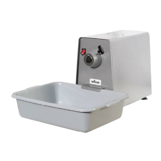
PM91 EXPLODED VIEW ........ - Page 3 OVERALL VIEW FIGURE 1 POWER UNIT POWER TAKE-OFF (PTO) POWER CORD THUMB SCREW CIRCUIT BREAKER (ON BACK) PLASTIC TUB POWER SWITCH TUB COVER (NOT SHOWN) PAGE II...
-
Page 4: Troubleshooting Guide
TROUBLESHOOTING GUIDE TROUBLE POSSIBLE CAUSE REMEDY 1.Power unit will not 1.1 Burned switch contacts. 1.1 Replace switch. operate. 1.2 Electrical service down. 1.2 Check electrical service. Replace fuse or reset circuit breaker if necessary. 1.3 Burned out motor. 1.3 Remove and replace motor. 2.Power unit is running 2.1 Broken or slipping belt. -
Page 5: Mechanics Maintenance
MECHANICS MAINTENANCE REMOVAL OF COVER The cover (Figure 2 [1]) must be removed to perform maintenance operations on the power unit. It is secured by two screws on the top and six Phillips pan head screws on the under side. 1. -
Page 6: Replacing The Drive Belt
REPLACING DRIVE BELT: 1. DISCONNECT THE ELECTRICAL POWER CORD. 2. Remove the cover per Mechanics Maintenance removal of cover on page 1.2. 3. Loosen the nuts on the front motor screws. Do not completely remove the nuts. 4. With a long screwdriver or a pry bar, raise the front of the motor and remove the belt from the upper pulley. -
Page 7: Pulley And Pto Removal
3. Remove the drive belt per the instructions on page 2.1 Replacing Drive Belt. 4. Loosen the two set screws in the driven pulley (Figure 2 [4]). NOTE: On the PM91 and MG8912, you must remove ether the motor or the PTO to get the driven pulley off. -
Page 8: Motor
MOTOR: REMOVAL: 1. DISCONNECT THE ELECTRICAL POWER CORD. 2. Remove the cover per Mechanics Maintenance removal of cover on page 1.2. 3. Remove the drive belt per the instructions on page 2.1 Replacing Drive Belt. 4. Remove the nuts (Figure 2 [14]) and washers [15] securing the motor and remove the spring [18] and upper isolator [17]. -
Page 9: Installation
MOTOR: INSTALLATION: 8. Place a 1 inch plastic sleeve on the two rear motor mounting studs (the longer studs). 9. Place a 1-1/8 inch plastic sleeve on the two front motor mounting studs. 10. Place a rubber isolator on the two rear motor mounting studs. 11. - Page 10 Front stud Rear stud Rubber isolators Front stud Front stud Spring Plastic sleeve Rubber isolators Nuts and washers Page 4.3...
-
Page 11: Tub Clip Removal
TUB CLIP: Only the PM91 incorporates a tub clip on the front of the power unit. Removal of the tub clip is as follows: 1. DISCONNECT THE ELECTRICAL POWER CORD. 2. Remove the cover per Mechanics Maintenance removal of cover on page 1.2. -
Page 12: Pm91
PTO Assembly P13020206 AND 8800012A PTO Adapter Set BEYOND USE 8700103A Tub Clip Assembly #4400229 8700106A Leg Kit PM91 7510094A Rubber Feet Set 8800100A Power Cord Assembly, 115V 8800100-2A Power Cord Assembly, 220V Motor Mounting Hardware Kit (Includes 14-20) 8700026A... - Page 13 PM91 ASSEMBLY FIGURE 2 Page 6.2...
-
Page 14: Pm91G
PM91G ASSEMBLY FIGURE 3 ILLUS. No. PART No. DESCRIPTION QTY. 8700002A Cover Assembly 1030308 Motor, 1HP, 115/230V, 60HZ, 1PH 1031309 Motor, 1HP, 220V, 50HZ, 1PH 8700025A Drive Set 8700010 Belt 8700025 Driven Pulley 4400230 8700024 Motor Pulley 8700035 On/Off Switch SERIAL # 8700019A Thumb Screw Assembly... - Page 15 PM91G ASSEMBLY FIGURE 3 Page 6.4...
-
Page 16: Mg8912
MG8912 ASSEMBLY FIGURE 4 ILLUS. No. PART No. DESCRIPTION QTY. 8700002A Cover Assembly 1030308 Motor, 1HP, 115/230V, 60HZ, 1PH 1031309 Motor, 1HP, 220V, 50HZ, 1PH 8700025A Drive Set 8700010 Belt 8700025 Driven Pulley 4400230 8700024 Motor Pulley 8700035 On/Off Switch 8700019A Thumb Screw Assembly SERIAL #... - Page 17 MG8912 ASSEMBLY FIGURE 4 Page 6.6...
-
Page 18: Vs2000
Thumb Screw Assembly P13020206 AND 4400045L PTO Assembly BEYOND USE 8800012A PTO Adapter Set #4400229 8700106A Leg Kit PM91 7510094A Rubber Feet Set 8800100A Power Cord Assembly, 115V 8800100-2A Power Cord Assembly, 220V Motor Mounting Hardware Kit (Includes 13-19) 8700026A... - Page 19 VS2000 ASSEMBLY FIGURE 5 Page 6.8...
- Page 20 3 Old Rockingham Road, Salem, N.H. 03079-2140 Telephone -603-893-6191 Fax 1-603-893-1249 TOLL FREE ORDERING FAX 1-800-356-5614...
Need help?
Do you have a question about the PM91 and is the answer not in the manual?
Questions and answers
DO YOU SELL PARTS FOR THE EQUIPMENT