
Related Manuals for YASKAWA Varispeed L7


Summary of Contents for YASKAWA Varispeed L7
-
Page 1: Parameter Description
Current Vector Controlled Inverter Varispeed L7 Instruction Manual and Parameter Description Model: CIMR-L7C http://nicontrols.com... - Page 2 N O R T H E R N INDUSTRIAL W W W . N I C O N T R O L S . C O M ESTABLISHED IN 1978 Northern Industrial Thwaites Close Blackburn Lancashire BB1 2QQ United Kingdom Cert No.
- Page 3 http://nicontrols.com...
- Page 4 Cables must not be connected or disconnected, nor signal tests carried out, while the power is switched on. The Varispeed L7 DC bus capacitor remains charged even after the power has been switched off. To avoid an electric shock hazard, disconnect the frequency inverter from the mains before carrying out maintenance.
- Page 5 Safety Precautions and Instructions for Use 1. General Please read these safety precautions and instructions for use thoroughly before installing and operating this inverter. Also read all of the warning signs on the inverter and ensure they are never damaged or removed. Live and hot inverter components may be accessible during operation.
- Page 6 This also applies to equipment with the CE mark. It is the responsibility of the manufacturer of the system or machine to ensure conformity with EMC limits. Your supplier or Yaskawa representative must be contacted when using leakage current circuit braker in con- junction with frequency inverters.
-
Page 7: Emc Compatibility
EMC Compatibility 1. Introduction This manual was compiled to help system manufacturers using Yaskawa frequency inverters to design and install electrical switchgear. It also describes the measures necessary to comply with the EMC Directive. The manual's installation and wiring instructions must therefore be followed. - Page 8 Ground clip Ground plate The grounding surfaces must be highly conductive bare metal. Remove any coats of varnish and paint. – Ground the cable shields at both ends. – Ground the motor of the machine. http://nicontrols.com...
- Page 9 Line Filters Recommended Line Filters for Varispeed L7 Inverter Model Line Filter Current Weight Dimensions Varispeed L7 Model (kg) W x D x H CIMR-L7C43P7 FS5972-10-07 141 x 46 x 330 CIMR-L7C44P0 FS5972-18-07 141 x 46 x 330 CIMR-L7C45P5 CIMR-L7C47P5...
- Page 10 Installation inverters and EMC filters Ground Bonds ( remove any paint ) Line Inverter Filter Load PE L1 Cable Length as short as possible Metal Plate Motor cable screened Ground Bonds ( remove any paint ) http://nicontrols.com...
- Page 11 Registered Trademarks The following registered trademarks are used in this manual. DeviceNet is a registered trademark of the ODVA (Open DeviceNet Vendors Association, • Inc.). InterBus is a registered trademark of Phoenix Contact Co. • Profibus is a registered trademark of Siemens AG. •...
-
Page 12: Table Of Contents
Handling Inverters This chapter describes the checks required upon receiving or installing an Inverter. Varispeed L7 Introduction ............1-2 Confirmations upon Delivery..........1-3 Exterior and Mounting Dimensions ........1-7 Checking and Controlling the Installation Site .......1-9 Installation Orientation and Space ........1-10 Removing and Attaching the Terminal Cover....... 1-11 Removing/Attaching the Digital Operator/Monitor and Front Cover ..................1-12... -
Page 13: Varispeed L7 Introduction
Varispeed L7 Introduction Varispeed L7 Models es: 200 V and 400 V. The maximum motor capacities The Varispeed L7 Series includes Inverters in two voltage class vary from 3.7 to 55 kW (23 models). Table 1.1 Varispeed L7 Models Specifications Varispeed L7 (Always specify through the protective structure when ordering.) -
Page 14: Confirmations Upon Delivery
If you find any irregularities in the above items, contact the agency from which you purchased the Inverter or your Yaskawa representative immediately. Nameplate Information There is a nameplate attached to the side of each Inverter. The nameplate shows the model number, specifica- tions, lot number, serial number, and other information on the Inverter. -
Page 15: Inverter Specifications
The model number of the Inverter on the nameplate indicates the specification, voltage class, and maximum motor capacity of the Inverter in alphanumeric codes. CIMR L7 A 2 3P7 Inverter Varispeed L7 Specification Max. Motor Capacity with IM drives (open loop Vector Control) 3.7 kW with IM drives (PG card are optional) 5.5 kW... -
Page 16: Component Names
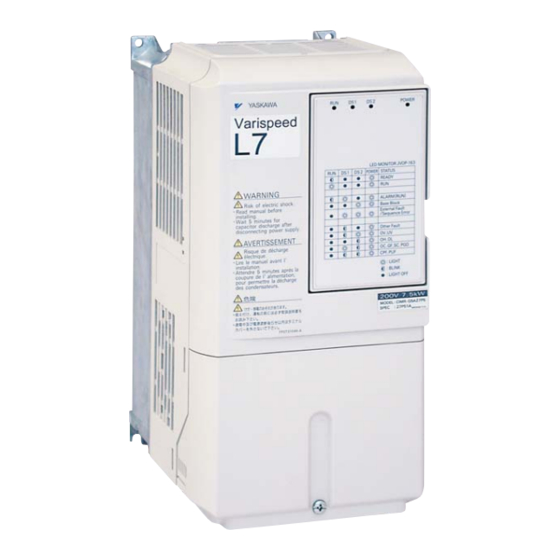
Confirmations upon Delivery Component Names Inverters of 18.5 kW or Less The external appearance and component names of the Inverter are shown in 1.4. The Inverter with the ter- minal cover removed is shown in 1.5. Mounting Front cover Diecast cover Digital Operator Nameplate Terminal cover... - Page 17 Inverters of 22 kW or More The external appearance and component names of the Inverter are shown in 1.6. The Inverter with the ter- minal cover removed is shown in 1.7. Inveter cover Mounting holes Cooling fan Front cover Nameplate Digital Operator Terminal cover Fig 1.6 Inverter Appearance (22 kW or More)
-
Page 18: Exterior And Mounting Dimensions
Exterior and Mounting Dimensions Exterior and Mounting Dimensions Open Chassis Inverters (IP00) Exterior diagrams of the Open Chassis Inverters are shown below. 200 V Class Inverters of 22 or 55 kW 200 V/400 V Class Inverters of 3.7 to 18.5 kW 400 V Class Inverters of 22 to 55 kW Fig 1.8 Exterior Diagrams of Open Chassis Inverters Enclosed Wall-mounted Inverters (NEMA1 IEC IP20) - Page 19 Table 1.3 Inverter Dimensions (mm) and Masses (kg) of 200V Class Inverters and 400V Class Inverters of 3.7 to 55 kW Dimensions (mm) Max. Applicable Open Chassis (IP00) Enclosed Wall-mounted (NEMA1and IEC IP20) Voltage Motor Class Output Approx. Approx. W1 W2 W3 H1 H2 D1 W1 H0 H1 H2 H3 D1 [kW] Mass...
-
Page 20: Checking And Controlling The Installation Site
Checking and Controlling the Installation Site Checking and Controlling the Installation Site Install the Inverter in the installation site described below and maintain optimum conditions. Installation Site Install the Inverter under the following conditions in a pollution degree 2 environment. Table 1.4 Installation Site Type Ambient Operating Temperature... -
Page 21: Installation Orientation And Space
Installation Orientation and Space Install the Inverter vertically so as not to reduce the cooling effect. When installing the Inverter, always provide the following installation space to allow normal heat dissipation. 30 mm min. 120 mm min. 30 mm min. 50 mm min. -
Page 22: Removing And Attaching The Terminal Cover
Removing and Attaching the Terminal Cover Removing and Attaching the Terminal Cover Remove the terminal cover to wire cables to the control circuit and main circuit terminals. Removing the Terminal Cover Inverters of 18.5 kW or Less Loosen the screw at the bottom of the terminal cover, press in on the sides of the terminal cover in the direc- tions of arrows 1, and then lift up on the terminal in the direction of arrow 2. -
Page 23: Removing/Attaching The Digital Operator/Monitor And
Removing/Attaching the Digital Operator/Monitor and Front Cover Inverters of 18.5 kW or Less To attach optional cards or change the terminal card connector, remove the Digital Operator/Monitor and front cover in addition to the terminal cover. Always remove the Digital Operator/Monitor from the front cover before removing the front cover. -
Page 24: Removing The Front Cover
Removing/Attaching the Digital Operator/Monitor and Front Cover Removing the Front Cover Press the left and right sides of the front cover in the directions of arrows 1 and lift the bottom of the cover in the direction of arrow 2 to remove the front cover as shown in the following illustration. Fig 1.14 Removing the Front Cover (Model CIMR-L7C43P7 Shown Above) Mounting the Front Cover After wiring the terminals, mount the front cover to the Inverter by performing the steps to remove the front... -
Page 25: Inverters Of 22 Kw Or More
1. Do not remove or attach the Digital Operator/Monitor or mount or remove the front cover using methods other than those described above, otherwise the Inverter may break or malfunction due to imperfect con- tact. 2. Never attach the front cover to the Inverter with the Digital Operator/Monitor attached to the front cover. Imperfect contact can result. - Page 26 Wiring This chapter describes wiring terminals, main circuit terminal connections, main circuit termi- nal wiring specifications, control circuit terminals, and control circuit wiring specifications. Connections to Peripheral Devices......2-2 Connection Diagram ............2-3 Terminal Block Configuration ........2-5 Wiring Main Circuit Terminals ........2-6 Wiring Control Circuit Terminals ........2-19 Wiring Check .............2-27 Installing and Wiring Option Cards ......2-28...
-
Page 27: Connections To Peripheral Devices
Connections to Peripheral Devices Examples of connections between the Inverter and typical peripheral devices are shown in 2.1. Power supply Molded-case circuit breaker Magnetic con- tactor (MC) AC reactor for power factor improvement Braking resistor Input noise filter DC reactor for power factor improvement Inverter Ground... -
Page 28: Connection Diagram
Connection Diagram Connection Diagram The connection diagram of the Inverter is shown in 2.2. When using the Digital Operator/Monitor, the motor can be operated by wiring only the main circuits. DC reactor to improve input Braking Resistor power factor unit (optional) (Optionnal) Short -circuit Magnetic... -
Page 29: Circuit Descriptions
Circuit Descriptions Refer to the numbers indicated in 2.2. These circuits are hazardous and are separated from accessible surfaces by protective separation These circuits are separated from all other circuits by protective separation consisting of double and reinforced insulation. These circuits may be interconnected with SELV (or equivalent) or non- SELV circuits, but not both. -
Page 30: Terminal Block Configuration
Terminal Block Configuration Terminal Block Configuration The terminal arrangements are shown in Fig 2.3 2.4. Control circuit terminals Main circuit terminals Charge indicator Ground terminal Fig 2.3 Terminal Arrangement (200 V/400 V Class Inverter of 3.7 kW) Control circuit terminals Charge indicator Main circuit... -
Page 31: Wiring Main Circuit Terminals
Wiring Main Circuit Terminals Applicable Wire Sizes and Closed-loop Connectors Select the appropriate wires and crimp terminals from Table 2.1 Table 2.3. Refer to instruction manual TOE-C726-2 for wire sizes for Braking Resistor Units and Braking Units. Table 2.1 200 V Class Wire Sizes Recom- Possible Inverter... - Page 32 Wiring Main Circuit Terminals Recom- Possible Inverter Tightening mended Termi- Wire Sizes Model Terminal Symbol Torque Wire Size Wire Type Screws CIMR- (N•m) (AWG) (AWG) 80 to 100 R/L1, S/L2, T/L3, 1 U/T1, 17.6 to 22.5 (3/0 to 4/0) (3/0) V/T2, W/T3, R1/L11, S1/L21, T1/L31, NO 5.5 to 22 8.8 to 10.8...
- Page 33 Recom- Possible Inverter Tightening mended Termi- Wire Sizes Model Terminal Symbol Torque Wire Size Wire Type Screws CIMR- (N•m) (AWG) (AWG) R/L1, S/L2, T/L3, 3, U/T1, V/T2, 4.0 to 5.0 W/T3, R1/L11, S1/L21, T1/L31, NO, PO L7C4030 22 to 38 9.0 to 10.0 (4 to 2) 22 to 60...
- Page 34 Wiring Main Circuit Terminals Table 2.3 Lug Sizes (JIS C2805) (200 V Class and 400 V Class) Terminal Screws Size Wire Thickness (mm M3.5 1.25 / 3.5 1.25 / 4 M3.5 1.25 / 3.5 0.75 1.25 / 4 M3.5 1.25 / 3.5 1.25 1.25 / 4 M3.5...
-
Page 35: Main Circuit Terminal Functions
Main Circuit Terminal Functions Main circuit terminal functions are summarized according to terminal symbols in Table 2.4. Wire the terminals correctly for the desired purposes. Table 2.4 Main Circuit Terminal Functions (200 V Class and 400 V Class) Model: CIMR-L7C Purpose Terminal Symbol 200 V Class... -
Page 36: Main Circuit Configurations
T1/L31 T1/L31 Power Control Power Control Supply Circuit Supply Circuit CIMR-L7C2037 to 2055 +3 +1 R/L1 U/T1 S/L2 T/L3 V/T2 R1/L11 W /T3 S1/L21 T1/L31 r/l1 Power Control Supply Circuit Note: Consult your Yaskawa representative before using 12-phase rectification. http://nicontrols.com... -
Page 37: Standard Connection Diagrams
Standard Connection Diagrams Standard Inverter connection diagrams are shown in 2.5. These are the same for both 200 V Class and 400 V Class Inverters. The connections depend on the Inverter capacity. CIMR-L7C23P7 to 2018 and 43P7 to 4018 CIMR-L7C2022, 2030, and 4022 to 4055 DC reactor Unit (optional) (optional) - Page 38 Wiring Main Circuit Terminals Wiring the Main Circuits This section describes wiring connections for the main circuit inputs and outputs. Wiring Main Circuit Inputs Observe the following precautions for the main circuit power supply input. Installing Fuses To protect the inverter, it is recommended to use semiconductor fuses like they are shown in the table below. Table 2.6 Input Fuses Inverter Type FUSE...
- Page 39 Installing a Moulded-case Circuit Breaker When connecting the power input terminals (R/L1, S/L2, and T/L3) to the power supply using a moulded-case circuit breaker (MCCB) observe that the circuit breaker is suitable for the Inverter. Choose an MCCB with a capacity of 1.5 to 2 times of the inverter's rated current. •...
- Page 40 Wiring Main Circuit Terminals Wiring the Output Side of Main Circuit Observe the following precautions when wiring the main output circuits. Connecting the Inverter and Motor Connect output terminals U/T1, V/T2, and W/T3 respective to the motor lead wires U, V, and W. Check that the motor rotates forward with the forward run command.
-
Page 41: Ground Wiring
Cable Length between Inverter and Motor The cable between the Inverter and motor is 30 m max. Ground Wiring Observe the following precautions when wiring the ground line. Always use the ground terminal of the 200 V Inverter with a ground resistance of less than 100 Ω and that •... - Page 42 Wiring Main Circuit Terminals 200 V and 400 V Class Inverters with 22 kW or higher Output Capacity CDBR Braking Unit Braking Resistor Unit Thermal overload Inverter relay contact Thermal overload relay contact Fig 2.7 Connecting the Braking Resistor and Braking Unit http://nicontrols.com...
- Page 43 Fig 2.8 Connecting Braking Units in Parallel Connecting the battery power supply Varispeed L7 is equipped with the cable for the battery power supply connection by the standard. Please detach the twisted-pair cable connected with main circuit terminal B1/+3 and -.
-
Page 44: Wiring Control Circuit Terminals
Wiring Control Circuit Terminals Wiring Control Circuit Terminals Wire Sizes For remote operation using analog signals, keep the control line length between the Analog Operator or oper- ation signals and the Inverter to 30 m or less, and separate the lines from main power lines or other control cir- cuits to reduce induction from peripheral devices. -
Page 45: Wiring Method
Wiring Control Circuit Terminals Fig 2.10 Straight Solderless Terminal Sizes Wiring Method Use the following procedure to connect wires to the terminal block. 1. Loosen the terminal screws with a thin-slot screwdriver. 2. Insert the wires from underneath the terminal block. 3. -
Page 46: Control Circuit Terminal Functions
Wiring Control Circuit Terminals Control Circuit Terminal Functions The functions of the control circuit terminals are shown in Table 2.10. Use the appropriate terminals for the correct purposes. Table 2.10 Control Circuit Terminals with default settings Terminal Signal Function Description Signal Level Type Forward run/stop... - Page 47 Table 2.10 Control Circuit Terminals with default settings (Continued) Terminal Signal Function Description Signal Level Type A phase positive pulse monitor A phase negative pulse monitor PG output PG output ratio ratio RS-422 level B phase positive pulse monitor B phase negative pulse monitor MEMOBUS Differential input PHC RS-422/...
- Page 48 Wiring Control Circuit Terminals Sinking/Sourcing Mode The input terminal logic can be switched between sinking mode (0-V common-NPN) and sourcing mode (+24V common-PNP) by using the jumper CN5. An external power supply is also supported, providing more freedom in signal input methods. Table 2.11 Sinking/Sourcing Mode and Input Signals External Power Supply –...
- Page 49 The setting of S1 switch on the control card Varispeed L7C control card has the S1 switch for selecting a encorder power supply voltage. Please select the appropriate voltage setting before connecting a motor encorder. The default setting is that both switches are ON position, which the power supply voltage is selected 5V DC.
-
Page 50: Control Circuit Terminal Connections
Wiring Control Circuit Terminals Control Circuit Terminal Connections Connections to Inverter control circuit terminals are shown in 2.15. Forward run/stop Reverse run/stop A(+) External Fault A(-) B(+) Fault Reset B(-) Multi-fanction Z(+) contact Inputs Multi f-step speed setting 1 Z(-) (Factory setting) Multi f-step speed setting 2 E(G) -
Page 51: Control Circuit Wiring Precautions
Control Circuit Wiring Precautions Observe the following precautions when wiring control circuits. Separate control circuit wiring from main circuit wiring (terminals R/L1, S/L2, T/L3, B1, B2, U/T1, V/T2, • W/T3, 2, and 3, PO, NO) and other high-power lines. Separate wiring for control circuit terminals MA, MB, MC, M1, M2, M3, M4, M5, and M6 (contact out- •... -
Page 52: Wiring Check
Wiring Check Wiring Check Checks Check all wiring after wiring has been completed. Do not perform continuity check on control circuits. Per- form the following checks on the wiring. Is all wiring correct? • Have no wire clippings, screws, or other foreign material been left? •... -
Page 53: Installing And Wiring Option Cards
Installing and Wiring Option Cards Option Card Models and Specifications Up to two Option Cards can be mounted on the controller card (C and D) shown in 2.16. Table 2.12 lists the type of Option Cards and their specifications. Table 2.12 Option Card Specifications Mounting Card Model... - Page 54 Installing and Wiring Option Cards Preventing C and D Option Card Connectors from Rising After installing an Option Card into slot C or D, insert an Option Clip to prevent the side with the connector from rising. The Option Clip can be easily removed by holding onto the protruding portion of the Clip and pulling it out.
- Page 55 http://nicontrols.com...
- Page 56 Digital Operator and Modes This chapter describes Digital Operator displays and functions, and provides an overview of operating modes and switching between modes. LED Monitor for JVOP-163 ...........3-2 Digital Operator.............3-3 uInverter Modes............3-5 http://nicontrols.com...
- Page 57 LED Monitor for JVOP-163 LED Monitor Indicators the operation status by the combination of the LED displays (Lights up, Blink, and Off) at RUN, DS1, and DS2. The LED pattern is as follows at each mode. Operation Mode Indicators RUN: Lights up during inverter run, Off if the inverter is stopped DS1: Drive Status 1...
-
Page 58: Digital Operator
Digital Operator Digital Operator This section describes the displays and functions of the Digital Operator. Digital Operator Display The key names and functions of the Digital Operator are described below. Drive Mode Indicators FWD: Lit when there is a forward run command input. REV: Lit when there is a reverse run command input. - Page 59 Table 3.1 Key Functions (Continued) Name Function Selects the rotation direction of the motor when the Inverter is being FWD/REV Key operated from the Digital Operator. Sets the number of digits for user constant settings. Shift/RESET Key Also acts as the Reset Key when a fault has occurred. Selects menu items, sets user constant numbers, and increments set Increment Key values.
-
Page 60: Inverter Modes
Digital Operator Inverter Modes The Inverter's parameters and monitoring functions are organized in groups called modes that make it easier to read and set parameters.The Inverter is equipped with 5 modes. The 5 modes and their primary functions are shown in the Table 3.2. -
Page 61: Switching Modes
Switching Modes The mode selection display will appear when the MENU key is pressed. Press the MENU key from the mode selection display to switch through the modes in sequence. Press the DATA/ENTER key to enter a mode and to switch from a monitor display to the setting display. Display at Startup -DRIVE- Frequency Ref... -
Page 62: Drive Mode
Digital Operator Drive Mode The Drive mode is the mode in which the Inverter can be operated. All monitor parameters (U1- ) as well as fault information and the fault history can be displayed in this mode When b1-01 (Reference selection) is set to 0, the frequency can be changed from the frequency setting display using the Increment, Decrement, and Shift/RESET keys. -
Page 63: Quick Programming Mode
Note: 1. When changing the display with the Increment / Decrement keys, the next display after the one for the last parameter number will be the one for the first parameter number and vice versa. For example, the next display after the one for U1-01 will be U1-40. This is indicated in the figures by the letters A and B and the numbers 1 to 6. -
Page 64: Advanced Programming Mode
Digital Operator Advanced Programming Mode In advanced programming mode all Inverter parameters can be monitored and set. A parameter can be changed from the setting displays using the Increment, Decrement, and Shift/RESET keys. The parameter will be saved and the display will return to monitor display when the DATA/ENTER key is pressed after changing the setting. - Page 65 Setting Parameters Here the procedure to change C1-01 (Acceleration Time 1) from 3.0 s to 4.0 s is shown. Table 3.3 Setting Parameters in Advanced Programming Mode Step Digital Operator Display Description -DRIVE- Frequency Ref U1- 01=60.00Hz Power supply turned ON. U1-02=60.00Hz U1-03=10.05A -DRIVE-...
-
Page 66: Verify Mode
Digital Operator Verify Mode The Verify mode is used to display any parameters that have been changed from their default settings in a pro- gramming mode or by autotuning. “None” will be displayed if no settings have been changed. The parameter A1-02 is the only parameter from the A1- group, which will be displayed in the modified contsant list if it has been changed before. -
Page 67: Autotuning Mode
Autotuning Mode Autotuning automatically measures and sets the required motor data in order to achieve the maximum perfor- mance. Always perform autotuning before starting operation when using the vector control modes. When V/f control has been selected, only stationary autotuning for line-to-line resistance can be selected. When the motor cannot be disconnected from the load, and Open Loop or Closed Loop Vector Control shall be used perform stationary autotuning. - Page 68 User Parameters This chapter describes all user parameters that can be set in the Inverter. User Parameter Descriptions........4-2 Digital Operation Display Functions and Levels ..4-3 User Parameter Tables ..........4-8 http://nicontrols.com...
-
Page 69: User Parameter Descriptions
User Parameter Descriptions This section describes the contents of the user parameter tables. Description of User Parameter Tables User parameter tables are structured as shown below. Here, b1-01 (Frequency Reference Selection) is used as an example. Control Methods MEMO- Name Change Param- Setting... - Page 70 Digital Operation Display Functions and Levels Digital Operation Display Functions and Levels The following figure shows the Digital Operator/Monitor display hierarchy for the Inverter. Function Page Status Monitor Parameters 4-50 Fault Trace 4-55 MENU Drive Mode 4-57 Fault History Initialize Mode Inverter can be operated and its status can be displayed.
- Page 71 User Parameters Setable in Quick Programming Mode The minimum user parameters required for Inverter operation can be monitored and set in quick programming mode. The user parameters displayed in quick programming mode are listed in the following table. These, and all other user parameters, are also displayed in advanced programming mode.
- Page 72 Digital Operation Display Functions and Levels Control Methods MEMO- Change Name Param- Setting Factory during Open Closed Description eter Range Setting Opera- Regis- Loop Loop Number Display tion Vector Vector ASR integral (I) time 1 Sets the integral time of the speed loop 0.000 to 0.500 s C5-02...
- Page 73 Control Methods MEMO- Change Name Param- Setting Factory during Open Closed Description eter Range Setting Opera- Regis- Loop Loop Number Display tion Vector Vector Max. output frequency 40.0 to (FMAX) E1-04 60.0 Hz 303H 120.0 Freqency Max. voltage 0.0 to 200.0 V (VMAX) E1-05...
- Page 74 Digital Operation Display Functions and Levels Control Methods MEMO- Change Name Param- Setting Factory during Open Closed Description eter Range Setting Opera- Regis- Loop Loop Number Display tion Vector Vector PG rotation 0: Phase A leads with forward run command. (Phase B leads with reverse run command.) F1-05 0 or 1...
-
Page 75: User Parameter Tables
User Parameter Tables A: Setup Settings Initialize Mode: A1 Control Methods Change MEMO- Name Param- Setting Factory during Open Closed Description Page eter Range Setting Opera- Loop Loop Number Display Register tion Vector Vector Language Used to select the language selection for displayed on the Digital Oper- Digital Oper-... - Page 76 User Parameter Tables Control Methods Change MEMO- Name Param- Setting Factory during Open Closed Description Page eter Range Setting Opera- Loop Loop Number Display Register tion Vector Vector Password Used to set a four digit number setting as the password. Usually this parameter is not displayed.
-
Page 77: Operation Mode Selections
Application Parameters: b Operation Mode Selections: b1 Name Control Methods Change MEMO- Param- Setting Factory during Open Closed Description Page eter Display Range Setting Opera- Loop Loop Number Register tion Vector Vector Reference Sets the frequency reference source selec- input method. tion 0: Digital Operator/Monitor 1: Control circuit terminal... -
Page 78: Dwell Functions
User Parameter Tables Timer Function: b4 User constants for timer functions are shown in the following table. Control Methods Change MEMO- Con- Open during Setting Factory Name Description Closed Page stant Loop Range Setting Opera- Loop Number Register Vec- tion Vector Sets the timer function output ON-delay time (dead band) for... -
Page 79: Acceleration/Deceleration
Tuning Parameters: C Acceleration/Deceleration: C1 Control Methods Change MEMO- Name Param- Setting Factory during Open Closed Description Page eter Range Setting Opera- Loop Loop Number Display Register tion Vector Vector Acceleration Sets the acceleration time to time 1 C1-01 accelerate from 0 Hz to the 200H 5-17 maximum output frequency. -
Page 80: S-Curve Acceleration/Deceleration
User Parameter Tables Control Methods Change MEMO- Name Param- Setting Factory during Open Closed Description Page eter Range Setting Opera- Loop Loop Number Display Register tion Vector Vector Accel/decel Sets the frequency for auto- time switch- matic acceleration/decelera- ing fre- tion switching. -
Page 81: Motor Slip Compensation
Motor Slip Compensation: C3 Control Methods Change MEMO- Name Param- Setting Factory during Open Closed Description Page eter Range Setting Opera- Loop Loop Number Display Register tion Vector Vector Used to improve speed accu- Slip compen- racy when operating with a sation gain load. -
Page 82: Torque Compensation
User Parameter Tables Torque Compensation: C4 Control Methods Change MEMO- Name Param- Setting Factory during Open Closed Description Page eter Range Setting Opera- Loop Loop Number Display Register tion Vector Vector Sets the torque compensation gain. Torque com- Usually changing this setting is pensation not necessary. -
Page 83: Speed Control (Asr)
Speed Control (ASR): C5 Name Control Methods Param- Change MEMO- eter Setting Factory during Open Closed Description Page Num- Display Range Setting Opera- Loop Loop Register tion Vector Vector ASR pro- portional 0.00 to Sets the proportional gain of the 40.00 (P) gain 1 C5-01... -
Page 84: Carrier Frequency
User Parameter Tables Carrier Frequency: C6 Control Methods MEMO- Param- Change Name eter Setting Factory during Description Open Closed Page Num- Range Setting Opera- Regis- Loop Loop Display tion Vector Vector Carrier fre- Selects the carrier frequency. quency Select F to enable detailed settings selection using parameters C6-03 to C6-05. -
Page 85: Preset Reference
Reference Parameters: d Preset Reference: d1 Control Methods Change MEMO- Name Param- Setting Factory during Open Closed Description Page eter Range Setting Opera- Loop Loop Number Display Register tion Vector Vector Frequency reference 1 d1-01 Sets the frequency reference. 0.00 Hz 280H Reference 1 Frequency... -
Page 86: Field Weakening
User Parameter Tables Control Methods Change MEMO- Name Param- Setting Factory during Open Closed Description Page eter Range Setting Opera- Loop Loop Number Display Register tion Vector Vector V3 reference Sets the frequency reference when multi-step speed com- d1-12 0.00 Hz 28DH mands 1, 2, and 4 are ON for V3 reference... -
Page 87: V/F Pattern
Motor Parameters: E V/f Pattern: E1 Control Methods MEMO- Param- Change Name eter Setting Factory during Description Open Closed Page Num- Range Setting Opera- Regis- Loop Loop Display tion Vector Vector Input volt- age setting Sets the Inverter input voltage. 155 to 200 V E1-01... -
Page 88: Motor Setup
User Parameter Tables * 2. The factory setting will change when the control method is changed. (The Open Loop Vector Control factory settings are given.) * 3. The factory setting will change when the control method is changed. (The Close Loop Vector Control factory settings are given.) * 4. - Page 89 Control Methods Change MEMO- Name Param- Setting Factory during Open Closed Description Page eter Range Setting Opera- Loop Loop Number Display Register tion Vector Vector Motor iron loss for torque com- 0 to 112 W E2-10 Sets motor iron losses. 317H 5-50 pensation...
-
Page 90: Pg Option Setup
User Parameter Tables Option Parameters: F PG Option Setup: F1 Control Methods Change MEMO- Name Param- Setting Factory during Open Closed Description Page eter Range Setting Opera- Loop Loop Number Display Register tion Vector Vector PG constant Sets the number of PG pulses 0 to F1-01 1024... - Page 91 Control Methods Change MEMO- Name Param- Setting Factory during Open Closed Description Page eter Range Setting Opera- Loop Loop Number Display Register tion Vector Vector PG division Sets the division ratio for the rate (PG PG speed control card pulse pulse moni- output.
- Page 92 User Parameter Tables Analog Monitor Cards: F4 User constants for the Analog Monitor Card are shown in the following table. Name Control Methods Change MEMO Con- Open Setting Factory during Description Closed stant Page Loop Range Setting Opera- Regis- Display Loop Number Vec-...
-
Page 93: Digital Output Card
Digital Output Card (DO-02 and DO-08): F5 User constants for the Digital Output Card are shown in the following table. Name Control Methods Change MEMO Con- Open Setting Factory during Description Closed stant Page Loop Range Setting Opera- Regis- Display Loop Number Vec-... - Page 94 User Parameter Tables Serial Communications Option card: F6 Control Methods Change MEMO- Name Param- Setting Factory during Open Closed Description eter Page Range Setting Opera- Loop Loop Number Display Register tion Vector Vector Operation Sets the stopping method for selection communications errors.
-
Page 95: Multi-Function Digital Inputs
Terminal Function Parameters: H Multi-function Digital Inputs: H1 Control Methods Change MEMO- Name Param- Setting Factory during Open Closed Description Page eter Range Setting Opera- Loop Loop Number Display Register tion Vector Vector Terminal S3 function selection H1-01 Multi-function input 1 0 to 88 400H Terminal S3... - Page 96 User Parameter Tables Control Methods Setting Open Closed Function Page Value Loop Loop Vector Vector External fault 20 to 2F Input mode: NO contact/NC contact, Detection mode: Normal/during operation Nominal Speed Reference Intermediate Speed Reference Releveling Speed Reference Leveling Speed Reference Inspection Run Command Battery Operation Command Output Contactor Answer Back Signal...
- Page 97 Control Methods Set- Open Closed ting Function Page loop Loop Value Vector Vector Run command source selection status (ON: Run command from Operator) 5-47 Overtorque/undertorque detection 1 NO (NO contact, ON: Overtorque/undertorque 5-47 detection) Loss of frequency reference (Effective when 1 is set for L4-05) 5-36 Braking resistor fault (ON: Resistor overheat or braking transistor fault) 5-37...
-
Page 98: Multi-Function Analog Inputs
User Parameter Tables Analog Inputs: H3 User constants for analog inputs are shown in the following table. Name Control Methods Change MEMO Con- Setting Factory during Open Close Description stant Page Range Setting Opera- Regis- Display Loop Loop Number tion Vector Vector Signal level... - Page 99 Name Control Methods Change MEMO Con- Setting Factory during Open Close Description stant Page Range Setting Opera- Regis- Display Loop Loop Number tion Vector Vector Gain (AI-14 Sets the input gain (level) CH2) when terminal 14 is 10 V (20 mA).
- Page 100 User Parameter Tables MEMOBUS Communications: H5 User constants for MEMOBUS communications are shown in the following table. Name Control Methods Change MEMO- Con- Open Setting Factory during Description Closed stant Page Loop Range Setting Opera- Regis- Display Loop Number Vec- tion Vector Station...
-
Page 101: Motor Overload
Protection Function Parameters: L Motor Overload: L1 Control Methods Change MEMO- Name Param- Setting Factory during Open Closed Description Page eter Range Setting Opera- Loop Loop Number Display Register tion Vector Vector Sets whether the motor thermal overload protection function is Motor pro- enabled or disabled. -
Page 102: Stall Prevention
User Parameter Tables Stall Prevention: L3 Control Methods Change MEMO- Name Param- Setting Factory during Open Closed Description eter Page Range Setting Opera- Loop Loop Number Display Register tion Vector Vector Stall preven- 0: Disabled (Acceleration as tion selec- set. With a heavy load, the tion during motor may stall.) accel... -
Page 103: Reference Detection
Reference Detection: L4 Control Methods MEMO- Param- Change Name eter Setting Factory during Description Open Closed Page Num- Range Setting Opera- Regis- Loop Loop Display tion Vector Vector Speed agree- Effective when "f agree ment detection 0.0 to 1", "Frequency detection 1" or level L4-01 120.0... -
Page 104: Torque Detection
User Parameter Tables Torque Detection: L6 Control Methods Change MEMO- Name Param- Setting Factory during Open Closed Description eter Page Range Setting Opera- Loop Loop Number Display Register tion Vector Vector 0: Overtorque/undertorque Torque detection disabled. detection 1: Overtorque detection only selection 1 with speed agreement;... -
Page 105: Torque Limits
Torque Limits: L7 Control Methods MEMO- Param- Change Name eter Setting Factory during Description Open Closed Page Num- Range Setting Opera- Regis- Loop Loop Display tion Vector Vector Forward drive torque limit 0 to L7-01 200%* 4A7H 5-37 Torq Limit Reverse drive Sets the torque limit value as a per-... -
Page 106: Hardware Protection
User Parameter Tables Hardware Protection: L8 Control Methods Change MEMO- Name Param- Setting Factory during Open Closed Description eter Page Range Setting Opera- Loop Loop Number Display Register tion Vector Vector Overheat pre- Sets the detection temperature alarm level for the Inverter overheat detec- tion pre-alarm in °C. -
Page 107: Automatic Frequency Regulator
Control Methods Change MEMO- Name Param- Setting Factory during Open Closed Description eter Page Range Setting Opera- Loop Loop Number Display Register tion Vector Vector OL2 charac- 0: OL2 characteristics at low teristics selec- speeds disabled. tion at low 1: OL2 characteristics at low L8-15 speeds speeds enabled. -
Page 108: Monitor Selection
User Parameter Tables Feed Forward: N5 User constants for the feed forward control are shown in the following table. Name Control Methods Change MEMO Con- Setting Factory during Open Closed Description stant Page Range Setting Opera- Regis- Display Loop Loop Number tion Vector... -
Page 109: Digital Operator/Monitor Functions
Control Methods Change MEMO- Name Param- Setting Factory during Open Closed Description eter Page Range Setting Opera- Loop Loop Number Display Register tion Vector Vector Frequency Sets the units that will be set units of refer- and displayed for the fre- ence setting quency reference and fre- and monitor... - Page 110 User Parameter Tables Control Methods Change MEMO- Name Param- Setting Factory during Open Closed Description eter Page Range Setting Opera- Loop Loop Number Display Register tion Vector Vector STOP key Enables/Disables the Stop key during con- in the run mode. trol circuit 0: Disabled (When the run terminal...
- Page 111 Control Methods Change MEMO- Name Param- Setting Factory during Open Closed Description eter Page Range Setting Opera- Loop Loop Number Display Register tion Vector Vector Fan opera- Sets the initial value of the fan tion time set- operation time. 0 to ting o2-10 The operation time is accumu-...
-
Page 112: Copy Function
User Parameter Tables Copy Function: o3 Control Methods Change MEMO- Name Param- Setting Factory during Open Closed Description Page eter Range Setting Opera- Loop Loop Number Display Register tion Vector Vector Copy func- 0: Normal operation tion selection 1: READ (Inverter to Operator) o3-01 0 to 3... - Page 113 Control Methods Change MEMO- Name Param- Setting Factory during Open Closed Description Page eter Range Setting Opera- Loop Loop Number Display Register tion Vector Vector SE2 detec- Used to set the time to detect tion delay SE2 fault in units of 1ms. time When the inverter output cur- S1-14...
- Page 114 User Parameter Tables Control Methods Change MEMO- Name Param- Setting Factory during Open Closed Description Page eter Range Setting Opera- Loop Loop Number Display Register tion Vector Vector Torque com- pensation 0.500 gain during Sets the torque compensation S1-23 1.000 6AAH lowering gain at lowering.
-
Page 115: Slip Compensation For Lift
S2 Slip compensation for lift Control Methods Change MEMO- Name Param- Setting Factory during Description Open Closed Page eter Range Setting Opera- Loop Loop Number Display Register tion Vector Vector Motor rated speed Sets the motor rated speed in 1380 S2-01 6AEH units of 1 rpm... -
Page 116: Motor Autotuning
User Parameter Tables T: Motor Autotuning Control Methods Change MEMO- Name Param- Setting Factory during Open Closed Description eter Page Range Setting Opera- Loop Loop Number Display Register tion Vector Vector Autotuning Sets the autotuning mode. mode selec- 0: Rotating autotuning tion T1-01 1: Non-rotating autotuning... -
Page 117: Status Monitor Parameters
U: Monitor Parameters Status Monitor Parameters: U1 Control Methods Output Signal Level Dur- Name MEMO- Param- Min. Description ing Multi-Function Ana- Open Closed eter Unit Loop Loop Number Display Register log Output Vector Vector Frequency reference Monitors/sets the frequency 10 V: Max. frequency 0.01 U1-01 reference value.*... - Page 118 User Parameter Tables Control Methods MEMO- Name Output Signal Level Param- Min. Description During Multi-Function Open Closed eter Unit Regis- Loop Loop Number Display Analog Output Vector Vector Input termi- Shows input ON/OFF status. nal status 1: FWD command (S1) is ON 1: REV command (S2) is ON 1: Multi input 1...
- Page 119 Control Methods MEMO- Name Output Signal Level Param- Min. Open Closed Description During Multi-Function eter Unit Regis- Loop Loop Number Display Analog Output Vector Vector Terminal A2 Monitors the input level of input level 10 V/20mA: 100% analog input A2. A value of U1-16 0.1% 100% corresponds to 10V/...
- Page 120 User Parameter Tables Control Methods MEMO- Name Output Signal Level Param- Min. Open Closed Description During Multi-Function eter Unit Regis- Loop Loop Number Display Analog Output Vector Vector OPE fault Shows the first parameter parameter U1-34 number when an OPE fault is (Cannot be output.) detected.
- Page 121 Control Methods MEMO- Name Output Signal Level Param- Min. Open Closed Description During Multi-Function eter Unit Regis- Loop Loop Number Display Analog Output Vector Vector Max Current during Top speed Monitors the maximum curr- 10 V: Rated current of motor U1-53 0.1 A net at top speed.
-
Page 122: Fault Trace
User Parameter Tables Fault Trace: U2 Control Methods Output Signal Level MEMO- Name Param- Min. Open Closed Description During Multi-Func- eter Unit Loop Loop Number Display Register tion Analog Output Vector Vector Current fault U2-01 The content of the current fault. Current Fault Last fault U2-02... - Page 123 Control Methods Output Signal Level MEMO- Name Param- Min. Open Closed Description During Multi-Func- eter Unit Loop Loop Number Display Register tion Analog Output Vector Vector Cumulative operation The operating time when the last U2-14 (Cannot be output.) time at fault fault occurred.
-
Page 124: Fault History
User Parameter Tables Fault History: U3 Output Signal Level Dur- Parame- Name Min. MEMOBUS Description ing Multi-Function Analog ter Num- Unit Register Display Output Last fault U3-01 The error content of 1st last fault. Last Fault Second last fault U3-02 The error content of 2nd last fault. - Page 125 Factory Settings that Change with the Control Method (A1-02) Factory Setting Param- Open Closed V/f Con- eter Name Setting Range Unit Loop Loop Num- trol Vector Vector A1-02=0 A1-02=2 A1-02=3 C3-01 Slip compensation gain 0.0 to 2.5 C3-02 Slip compensation delay time 0 to 10000 2000 C4-02 Torque compensation delay time constant...
- Page 126 User Parameter Tables 200 V and 400 V Class Inverters of 3.7 to 45 kW* Para meter Factory Setting Open Closed Unit Num- Loop Loop Vector Vector Control Control E1-03 E1-04 50.0 60.0 60.0 72.0 50.0 50.0 60.0 60.0 50.0 50.0 60.0 60.0...
- Page 127 Factory Settings that Change with the Inverter Capacity (o2-04) 200 V Class Inverters Parameter Factory Setting Name Unit Number Inverter Capacity 18.5 o2-04 kVA selection E2-01 Motor rated current 14.00 19.60 26.60 39.7 53.0 65.8 77.2 (E4-01) E2-02 Motor rated slip 2.73 1.50 1.30...
- Page 128 User Parameter Tables 400 V Class Inverters Parameter Factory Setting Name Unit Number Inverter Capacity o2-04 kVA selection E2-01 Motor rated current 7.00 7.00 9.80 13.30 19.9 26.5 (E4-01) E2-02 Motor rated slip 2.70 2.70 1.50 1.30 1.70 1.60 (E4-02) E2-03 Motor no-load current 2.30...
- Page 129 http://nicontrols.com...
- Page 130 Parameter Settings by Function Current Derating and Limitation related to the Carrier Fre- quency ................5-2 Control Sequence ............5-4 Acceleration and Deceleration Characteristics ..5-17 Adjusting Analog Input Signals ........5-22 Speed Detection and Speed Limitation......5-23 Improving the Operation Performance.......5-26 Protective Functions ..........5-34 Inverter Protection .............5-40 Input Terminal Functions..........5-43 Output Terminal Functions.........5-47...
-
Page 131: Current Derating And Limitation Related To The Carrier Frequency
Current Derating and Limitation related to the Carrier Frequency The inverter rated current derating and limitation are changed by carrier frequency setting. Related Parameters Control Methods Change Parameter Factory during Open Closed Name Setting Opera- Loop Loop tion Vector Vector C6-02 Carrier frequency selection 3 (8 kHz) - Page 132 Current Derating and Limitation related to the Carrier Frequency Current limit level Varispeed L7 limits the output current at low frequencies. Current limit level that change with the inverter capacity. The current limitation in the low frequency is as follows.
-
Page 133: Control Sequence
Control Sequence Run Commands To start the elevator in Up or Down direction, the following conditions have to be fulfilled: Speed reference must be selected. • The hardware base block signal must be released (not base block condition). • The contactor confirmation signal must be closed when it is selected. •... - Page 134 Control Sequence Forward/Reverse Commands Using an Input Option Card (b1-02=3) When b1-02 is set to 3 the Forward/Reverse command can be set using an input option card, for example a field bus communications card. Speed Reference Source Selection Speed Reference Source Selection The speed reference source can be selected using parameter b1-01.
-
Page 135: Speed Selection Sequence Using Digital Inputs
Speed Selection Sequence Using Digital Inputs If the digtal inputs are used for speed selection, the speed selection method and the speed priority depends on the setting of parameter d1-18. Control Methods Change Parameter Factory Open Closed Name during Setting Loop Loop Operation... - Page 136 Control Sequence Separate Speed Selection Inputs, High Speed Has Priority (d1-18=1) With this setting 6 different speeds can be set and selected using four digital inputs. Related Parameters Control Methods Change Digital Input Parameter Factory Open Closed Name during Setting (H1-01 to Setting Loop Loop...
- Page 137 Higher Speed Priority is Selected and no Leveling Speed Input is Selected (H1- =83) When the leveling speed command is not selected for any digital input, the inverter decelerates to the leveling speed (d1-17) when all selected speed signals are removed. The selected speed must be different from leveling and inspection speed.
- Page 138 Control Sequence The following speed selection table shows the different speeds and the according digital inputs. Nominal Intermed. Intermed. Intermed. Relevel. Leveling Terminal function Speed Speed 1 Speed 2 Speed 3 Speed Speed d1-09 d1-10 d1-11 d1-12 d1-13 d1-17 × Nominal Speed command (H1- =80) ×...
-
Page 139: Emergency Stop
Emergency Stop If a digital input terminal (H1- ) is set to 15 or 17 (emergency stop), this input can be used to fast stop the inverter in the case of emergency. In this case the emergency stop deceleration time set in C1-09 is used. If inputting the emergency stop with an NO contact, set the multi-function input terminal (H1- ) to 15, and if inputting the emergency stop with an NC contact, set the multi-function input terminal (H1-... -
Page 140: Brake Sequence
Control Sequence The inpspection run command must be set before setting the Forward/Reverse signal. During start of the inspection RUN the normal brake sequence is used and the inverter accelerates to the inspection speed (d1-14). To stop the inverter, the Inspection Run command or the Forward/Reverse command must be removed. In this case: The inverter output is cut by baseblock immediately •... - Page 141 Multi-function Digital Inputs (H1-01 to H1-05) Control Methods Open Closed Set Value Function Loop Loop Vector Vector Speed selection inputs (refer to <Cross Ref 8>page 5-6, Speed Selection Sequence Using 80 to 83 Digital Inputs) Contactor closed answer back signal Multi-function Digital Outputs (H2-01 to H2-03) Control Methods Open...
- Page 142 Control Sequence The timing chart above is divided in time zones. The following table explains the sequence in each time zone. Timing Description The inverter gets the direction signal (Forward/Reverse) The inverter gets the hardware base block disable signal (Not BB condition). The inverter receives the speed reference signal.
- Page 143 Brake Sequence with torque compensation at start This sequence works in Closed Loop Vector control only. To use the brake sequence with torque compensation at start, the A1 function must be selected for “Torque compensation” (H3-15=1) or • one of the input channels Ch2 or Ch3 of the optional analog input card AI-14B must be set to “Torque •...
- Page 144 Control Sequence Timing Description The inverter continues zero speed operation until the time S1-05 – S1-07 time be passed. t8-t9 Remove the direction signal . The inverter shuts down the output voltage and the hardware base block signal must be set. t9-t10 After the “Output contactor open delay time”...
- Page 145 Short Floor Operation Related parameters Control Methods Change Parameter Factory Open Closed Name during Setting Loop Loop Operation Vector Vector S3-01 Short floor operation Princple The short floor operation is activated when the leveling signal is set before the nominal speed was reached. The inverter calculates the distance for deceleration from nominal speed to the levelings speed, which is equal to the area S in the figure below..
-
Page 146: Acceleration And Deceleration Characteristics
Acceleration and Deceleration Characteristics Acceleration and Deceleration Characteristics Setting Acceleration and Deceleration Times The acceleration time indicates the time to increase the speed from 0% to 100% of the maximum speed set in E1-04. The deceleration time indicates the time to decrease the speed from 100% to 0% of E1-04. Four separate acceleration and deceleration times can be set. - Page 147 Switching Acceleration and Deceleration Time Using Multi-Function Input Terminal Commands When two digital input terminals are set for “Accel./Decel. time switch over 1 and 2” (H1- =7 and 1A), the acceleration/deceleration times can be switched over even during operation by combining the ON/OFF status of the terminals.
- Page 148 Acceleration and Deceleration Characteristics Acceleration and S-curve Settings Five different S-curve times are used to reduce the jerk when the speed changes. Related Parameters Control Methods Change Parameter Factory during Open Closed Name Setting Opera- Loop Loop tion Vector Vector C2-01 S-curve characteristic time at acceleration start 0.5 s...
- Page 149 Output Speed Hold (Dwell Function) The dwell function holds the speed temporarily. Related Parameters Control Methods Change Parameter Factory Open Closed Name during Setting Loop Loop Operation Vector Vector b6-01 Dwell frequency at start 0.0 Hz b6-02 Dwell time at start 0.0 s b6-03 Dwell frequency at stop...
- Page 150 Acceleration and Deceleration Characteristics Stall Prevention During Acceleration The Stall Prevention During Acceleration function prevents the motor from stalling if the load is too heavy. If L3-01 is set to 1 (enabled) and the Inverter output current reaches 85 % of the set value in L3-02, the accel- eration rate will begin to slow down.
-
Page 151: Adjusting Analog Input Signals
Adjusting Analog Input Signals Adjusting Analog Frequency References Using the H3- parameters, the analog input values of terminal A1 or the Channels 1 to 3 of the optional analog input card AI-14B can be adjusted. Related Parameters Control Methods Change Parameter Factory Open... -
Page 152: Speed Detection And Speed Limitation
Speed Detection and Speed Limitation Speed Detection and Speed Limitation Speed Agreement Function There are eight different types of frequency detection methods available. The digital outputs M1 to M6 can be programmed for this function and can be used to indicate a frequency detection or agreement to any external equipment. - Page 153 Time Charts The following table shows the time charts for each of the speed agreement functions. Related L4-01: Speed Agree Level L4-03: Speed Agree Level +/– parameter L4-02: Speed Agree Width L4-04: Speed Agree Width Agree 2 Agree 1 Frequency Frequency reference reference...
- Page 154 Speed Detection and Speed Limitation Limiting the Elevator Speed To use the high speed limit of UP direction or DOWN direction , one of the digital inputs must be set for “ High speed limit switch Up” or “Down” (H1- = 87/88).
-
Page 155: Improving The Operation Performance
Improving the Operation Performance Reducing the Motor Speed Fluctuation (Slip Compensation Function) When the load is large, the motor slip also grows and the motor speed decreases. The slip compensation func- tion keeps the motor speed constant, regardless of changes in load. When the motor is operating at the rated load, parameter E2-02 (Motor Rated Slip) ×... - Page 156 Improving the Operation Performance Adjusting Slip Compensation Limit (C3-03) Using parameter C3-03 the upper limit for the slip compensation can be set as a percentage, taking the motor rated slip as 100%. If the speed is lower than the target value but does not change even after adjusting the slip compensation gain, the slip compensation limit may have been reached.
- Page 157 Related Parameters Control Methods Change Parameter Factory Open Closed Name during Setting Loop Loop Operation Vector Vector C4-01 Torque compensation gain 1.00 C4-02 Torque compensation delay time constant 2000 ms C4-03 Starting torque compensation value (forward direction) C4-04 Starting torque compensation value (reverse direction) C4-05 Starting torque compensation time constant 1 ms...
- Page 158 Improving the Operation Performance Starting Torque Compensation Function (C4-03 to C4-05) A starting torque compensation can be applied to speed up the torque establishment at start in Open Loop Vec- tor control. It works like shown in the following diagram. Forward (Reverse) Run command Time constant: C4-02 Time constant: C4-05...
- Page 159 ASR Gain and Integral Time Adjustments There are three sets of ASR gain and bias, one for the maximum speed (C5-01/02), one the minimum speed for acceleration (C5-03/04) and one for the minmum speed for deceleration (C5-09/10) (see the figure below). ASR P,I ASR P,I C5-09 ASR Gain 3...
- Page 160 Improving the Operation Performance Stabilizing Speed (Automatic Frequency Regulator) (Open Loop Vector) The speed feedback detection control (AFR) function controls the stability of the speed when a load is sud- denly applied or removed. It calculates the amount of speed fluctuation using the torque current (Iq) feedback value and compensates the output frequency with the amount of fluctuation.
- Page 161 Adjustments Motor acceleration time (n5-02) The motor acceleration time n5-02 the time which is needed to accelerate to rated speed with the rated torque of the motor. The time can be estimated like follows: Make the general setup (V/f pattern, Motor Setup, etc.) •...
-
Page 162: Field Forcing
Improving the Operation Performance Adjustments The Slip compensation values can be set separately for motoring and regenerative operation. Before adjusting this function the general setup should have been done (Motor Setup, V/f pattern, Speeds, ASR settings etc.). To adjust the Slip compesation function do the following in motoring and regenerative mode: Set the motor speed in S2-01 if V/f control is used. -
Page 163: Protective Functions
Protective Functions Preventing Motor Stalling During Operation Stall prevention during operation prevents the motor from stalling by automatically lowering the inverter out- put frequency when a transient overload occurs while the motor is operating at a constant speed. Stall prevention during operation can be enabled in V/f control only. If the Inverter output current continues to exceed the setting in parameter L3-06 for 100 ms or longer, the motor speed is reduced. - Page 164 Protective Functions Related Parameters Control Methods Change Parameter Factory Open Closed Name during Setting Loop Loop Operation Vector Vector L6-01 Torque detection selection 1 L6-02 Torque detection level 1 150% L6-03 Torque detection time 1 10.0 s L6-04 Torque detection selection 2 L6-05 Torque detection level 2 150%...
- Page 165 Timing Charts Fig 5.14 Fig 5.15 show the timing charts for overtorque and undertorque detection. Motor current (output torque) L6-02 or L6-05 L6-03 or L6-03 or Overtorque detection 1 NO L6-06 L6-06 or overtorque detection 2 NO *Overtorque detection switch off bandwidth is approximately 10% of the Inverter rated output current (or motor rated torque).
- Page 166 Protective Functions Limiting Motor Torque (Torque Limit Function) This function allows limitation of motor shaft torque independendly for each of the four quadrants. The torque limit can be set as fixed value using parameters or as variable value using an analog input. The torque limit function can be used with Open Loop Vector and Closed Loop Vector control only.
-
Page 167: Motor Overload Protection
Enabling Integral Torque Limit Operation (L7-06 and L7-07) In Open Loop Vector control an integral operation can be applied to the torque limit function (P-control is standard). This improves the torque limit responsiveness and smoothes the torque limit operation. To enable the integral operation set paramter L7-07 to 1. - Page 168 Protective Functions Setting Motor Protection Operation Time (L1-02) The motor protection operation time is the time for that the motor can handle a 150% overload when it was running with the rated load before (i.e. operating temperature was reached before applying the 150% over- load).
-
Page 169: Inverter Protection
Inverter Protection Inverter Overheat Protection The Inverter is protected against overheating using a thermistor that detects the heatsink temperature. When the overheat temperature level is reached the inverter output is switched off. To prevent a suddenly and unexpected stop of the inverter due to an overtemperature, an overheating pre-alarm can be output. -
Page 170: Output Open Phase Protection
Inverter Protection Output Open Phase Protection This function detects an open output phase by comparing the output current value of each phase with an inter- nal set output open phase detection level (5% of inverter rated current). The detection will not work when the output frequency is below 2% of the base frequency. -
Page 171: Cooling Fan Control
Cooling Fan Control This function controls the fan which is mounted to the inverters heatsink. Related Parameters Control Methods Change Parameter Factory Open Closed Name during Setting Loop Loop Operation Vector Vector L8-10 Cooling fan control selection L8-11 Cooling fan control delay time 60 s Selecting the Cooling Fan Control Using parameter L8-10 two modes can be selected:... -
Page 172: Input Terminal Functions
Input Terminal Functions Input Terminal Functions The digital multifunction inputs can be set for several functions using the H1-01 to H1-05 parameters (termi- nal S3 to S7 function selection). These following section describes the input functions not mentioned in any other section. -
Page 173: Using The Timer Function
The following table shows the relationship between the external fault conditions and the set value in H1- Input Level Error Detection Method Operation During Error Detection (See Note 1.) (See Note 2.) Detection Continue Value Constant Decelerate to Coast to Stop Emergency NO Contact NC Contact... - Page 174 Input Terminal Functions Multi-function Digital Inputs (H1-01 to H1-05) Control Methods Open Closed Function Value Loop Loop Vector Vector Timer function input Multifunction Outputs (H2-01 to H2-03) Control Methods Open Closed Function Value Loop Loop Vector Vector Timer function output Setting Example When the timer function input ON time is longer than the value set in b4-01, the timer output function is turned ON.
- Page 175 Output Contactor Answer Back Detetcion The output contactors can be observed using the output contactor answer back function. Therefore an auxil- liary contact of the motor contactors must be connected to a digital input which is set to for this function (H1- =86).
-
Page 176: Output Terminal Functions
Output Terminal Functions Output Terminal Functions The digital multifunction outputs can be set for several functions using the H2-01 to H2-03 parameters (termi- nal M1 to M6 function selection). These functions are described in the following section. Related Parameters Control Methods Change Parameter Factory... - Page 177 Inverter Operation Ready (Setting: 6) If a multifunction output is programmed for this function the output will be switched ON when the initialisa- tion of the inverter at startup has finished without any faults. During DC Bus Undervoltage (Setting: 7) If a multifunction output is programmed for this function the output is switched ON as long as a DC bus und- ervoltage is detected.
- Page 178 Output Terminal Functions During Regenerative Operation (Setting: 1D) If a multifunction output is programmed for this function the output is switched ON when the motor works regenerative, i.e. when energy is feedback to the inverter. Speed Detection at decelerattion (Door Zone) (Setting:42) This output can be used to detect, that the car is in the door zone.
-
Page 179: Motor And V/F Pattern Setup
Set E2-03 to the motor no-load current at the rated voltage and rated frequency. Normally, the motor no-load current is not written on the motor nameplate. Consult the motor manufacturer. Factory setting is the no-load current value for a standard Yaskawa 4-pole motor. Number of Motor Poles Setting (E2-04) E2-04 is displayed only when Closed Loop Vector control method is selected. - Page 180 Motor and V/f Pattern Setup Motor Line-to-Line Resistance Setting (E2-05) E2-05 is set automatically when performing motor line-to-line resistance autotuning. When you cannot per- form tuning, consult the motor manufacturer for the line-to-line resistance value. Calculate the resistance from the line-to-line resistance value in the motor test report using the following formula, and then make the setting accordingly.
- Page 181 Setting the V/f Pattern 1 Using the E1- parameters the Inverter input voltage and the V/f pattern can be set as needed. It is not rec- ommended to change the settings when the motor is used in Open Loop or Closed Loop vector control mode. Related Parameters Change Control Methods...
- Page 182 Motor and V/f Pattern Setup Setting the V/f Pattern If E1-03 is set to F the V/f pattern can be set individually using the parameters E1-04 to E1-10. See Fig 5.23 for details. Output voltage (V) Frequency (Hz) Fig 5.23 V/f pattern setting To set the V/f characteristics linear, set E1-07 and E1-09 to the same value.
-
Page 183: Digital Operator/Monitor Functions
Digital Operator/Monitor Functions Setting Digital Operator/Monitor Functions Related Parameters Control Methods Change Parameter Factory during Open Closed Name Setting Opera- Loop Loop tion Vector Vector o1-01 Monitor selection o1-02 Monitor selection after power up o1-03 Frequency units of reference setting and monitor o1-04 Setting unit for frequency reference related parameters o1-05... - Page 184 Digital Operator/Monitor Functions Changing the Units for Frequency Parameters Related to V/f settings (o1-04) Using parameter o1-04 the unit for frequency parameters related to the V/f setting can be changed. If o1-04 is set to 0 it will be Hz. If o1-04 is set to 1 it will be rpm. Changing the Display Contrast (o1-05) Using o1-05 the contrast of the LCD display on the digital operator can be raised or lowered.
- Page 185 Cooling Fan Operation Time (o2-10) This function counts the operating time of the inverter mounted fan cumulatively. Using parameter o2-10 the counter can be reset, e.g. when the fan was replaced. Fault Trace Initialize (o2-12) This function can be used to initialize the fault trace by setting parameter o2-12 to 1. “Number of Travels”...
- Page 186 Digital Operator/Monitor Functions Storing Inverter set values in the Digital Operator/Monitor (READ) To store Inverter set values in the Digital Operator/Monitor use the following method. Table 5.1 READ Function Procedure Step Digital Operator/Monitor Dis- Explanation play -ADV- ** Main Menu ** Press the Menu Key and select advanced programming mode.
- Page 187 Writing Parameter Set Values Stored in the Digital Operator/Monitor to the Inverter (COPY) To write parameter set values stored in the Digital Operator/Monitor to the Inverter, use the following method. Table 5.2 COPY Function Procedure Step Digital Operator/Monitor Dis- Explanation play -ADV- ** Main Menu **...
- Page 188 Digital Operator/Monitor Functions Comparing Inverter Parameters and Digital Operator/Monitor Parameter Set Values (VERIFY) To compare Inverter parameters and Digital Operator/Monitor parameter set values, use the following method. Table 5.3 VERIFY Function Procedure Step Digital Operator/Monitor Dis- Explanation play -ADV- ** Main Menu ** Press the MENU Key.
-
Page 189: Prohibiting Overwriting Of Parameters
Prohibiting Overwriting of Parameters If A1-01 is set to 0, all parameters except A1-01 and A1-04 are write protected, U1- , U2- will be displayed. If A1-01 is set to 1, only the parameters A1-01, A1-04 and A2- can be read or written, U1- , U2- and U3-... - Page 190 Digital Operator/Monitor Functions Displaying User-set Parameters Only The A2 parameters (user-set parameters) and A1-01 (parameter access level) can be used to establish a param- eter set that contains only the most important parameters. Set the number of the parameter to refer in A2-01 to A2-32, and then set A1-01 to 1. Using the advanced pro- gramming mode A1-01 to A1-03 and the parameters set in A2-01 to A2-32 can be read and modified.
-
Page 191: Pg Interface
PG Interface To get a more precise speed control the inverter has PG interface to connect a pulse generator. Related Parameters Control Methods Change Parameter Factory during Open Closed Name Setting Opera- Loop Loop tion Vector Vector F1-01 PG constant 1024 F1-02 Operation selection at PG open circuit (PGO) - Page 192 PG Interface Setting PG Pulse Monitor Output Dividing Ratio (F1-06) This function is enabled only when using PG speed control card PG-B2. Set the dividing ratio for the PG pulse monitor output. The set value is expressed as n for the higher place digit, and m for the two lower place digits. The dividing ratio is calculated as follows: Dividing ratio = (1 + n)/m (Setting range) n: 0 or 1, m: 1 to 32 F1-06 =...
-
Page 193: Battery Operation
Battery Operation Using battery operation the car can be moved to the next floor if the power supply fails. The battery operation, must be enabled by a digital input (H1- = 85). The battery voltage must be set in parameter L2-11. Related Constants. - Page 194 Battery Operation Battery sequence The following timing chart shows the sequence of battery operation. Battery voltage UV det level Coasting battery voltage x base speed 300(600 *1 )x2 Motor speed Brake *1: 400VClass using 600V Fault C,D input contactor Approx. 1min The power source of Battery operation these contactors must...
-
Page 195: Battery Selection
Battery selection Use the following battery 200V Class 400V Class Main bus voltage more than 48V more than 96V Control voltage 200V 400V Note Main bus voltage during battery operation is decided based on the 10% of motor base speed. Voltage drop must be less than 5% under the following load condition. -
Page 196: Automatic Fault Restart
Automatic Fault Restart Automatic Fault Restart The inverter can be set to restart automatically after a fault occurs. The maximum number of restarts can be selected. Auto-resetable Fault codes are: UV1, GF, OC, OV, OL2, OL3, OL4, UL3, UL4, PF, LF Related Constants. - Page 197 http://nicontrols.com...
- Page 198 Troubleshooting This chapter describes the fault displays and countermeasures for Inverter and motor problems. Protective and Diagnostic Functions ......6-2 Troubleshooting ............6-17 http://nicontrols.com...
-
Page 199: Protective And Diagnostic Functions
Protective and Diagnostic Functions This section describes the fault and alarm functions of the Inverter. These functions include fault detec- tion, alarm detection, operatot programming error detection and auto-tuning error detection. Fault Detection When the Inverter detects a fault, the fault contact output operates and the Inverter output is switched OFF causing the motor to coast to stop. - Page 200 Protective and Diagnostic Functions Table 6.1 Fault Detection (Continued) Display Meaning Probable Causes Corrective Actions The voltage fluctuations of the power supply are too high. Check the input voltage. A momentary power loss DC Bus Undervoltage occurred. The DC bus voltage is below the Undervoltage Detection Level The terminal screws of the input Check the wiring of the input...
- Page 201 Table 6.1 Fault Detection (Continued) Display Meaning Probable Causes Corrective Actions The ambient temperature is too Check for dirt build-up on the high. fans or heatsink. Heatsink Overheat The temperature of the Inverter's Reduce the ambient tempera- There is a heat source nearby. cooling fin exceeded the setting in ture around the drive.
- Page 202 Protective and Diagnostic Functions Table 6.1 Fault Detection (Continued) Display Meaning Probable Causes Corrective Actions Undertorque Detection 1 Ensure the values in L6-02 The Inverter’s output current (V/f and L6-03 are appropriate. control) or the output torque (Vec- Motor was underloaded. Undertorq Det 1 tor control) fell below L6-02 for Check application/machine...
- Page 203 Table 6.1 Fault Detection (Continued) Display Meaning Probable Causes Corrective Actions External fault at terminal S3 Ext Fault S3 External fault at terminal S4 Ext Fault S4 An "external fault" was input Eliminate the cause of the External fault at terminal S5 from a multi-function input termi- Ext Fault S5 external fault condition.
- Page 204 Protective and Diagnostic Functions Table 6.1 Fault Detection (Continued) Display Meaning Probable Causes Corrective Actions Perform an initialization to factory defaults. Baseblock circuit error CPF02 Gate array hardware failure at A baseblock circuit error occurred Cycle the power to the BB Circuit Err power-up.
- Page 205 Table 6.1 Fault Detection (Continued) Display Meaning Probable Causes Corrective Actions Perform an initialization to factory defaults. Noise or spike was on the com- Cycle the power to the CPF21 Self-diagnosis Fault of munication line and/or defective Inverter Option CPU Down Option Board option board.
-
Page 206: Alarm Detection
Protective and Diagnostic Functions Alarm Detection Alarms are Inverter protection function that do not operate the fault contact output. The system will automati- cally return to its original status when the cause of the alarm has been removed. During an alarm condition, the Digital Operator/Monitor display flashes and an alarm ouput is generated at the multi-function outputs (H2-01 to H2-03) if programmed When an alarm occurs, take appropriate countermeasures according to the table below. - Page 207 Table 6.2 Alarm Detection Display Meaning Probable causes Corrective Actions Recheck the cycle time and the size of the load. Motor Overheating Alarm Recheck the accel and decel Detected when the level at A2, times (C1- programmed for motor tempera- Overheating of the motor as mea- Motor Overheat 1 ture (Thermistor input, H3-09 =...
- Page 208 Protective and Diagnostic Functions Table 6.2 Alarm Detection Display Meaning Probable causes Corrective Actions The load is too large. Reduce the load. Excessive Speed Deviation The acceleration time and decel- Lengthen the acceleration time Detected when F1-04 = 3 and eration time are too short.
-
Page 209: Operator Programming Errors
Operator Programming Errors An Operator Programming Error (OPE) occurs when an inapplicable parameter is set or an individual param- eter setting is inappropriate. The Inverter will not operate until the parameter is set correctly; however, no alarm or fault outputs will occur. If an OPE occurs, change the appropriate parameter by checking the cause shown in Table 7.3. - Page 210 Protective and Diagnostic Functions Table 6.3 Operator Programming Errors (Continued) Display Meaning Probable Causes Corrective Actions One of the control methods need- Verify the control method OPE06 ing a PG feedback was selected selection in parameter A1-02 Control method selection error PG Opt Missing (A1-02 = 1 or 3), but a PG option and/or the installation of the...
- Page 211 Auto-tuning Fault Auto-tuning faults are shown below. When the following faults are detected, the fault is displayed on the digi- tal operator and the motor coasts to stop. No fault or alarm outputs will be operated. Table 6.4 Auto-tuning Fault Display Meaning Probable causes...
- Page 212 Protective and Diagnostic Functions Table 6.4 Auto-tuning Fault Display Meaning Probable causes Corrective Actions Auto-tuning was not completed in Er - 13 the specified time. Leakage Induc- Leakage Inductance Fault Check motor wiring. Auto-tuning result is outside the tance Fault parameter setting range.
- Page 213 Digital Operator/Monitor Copy Function Faults These faults can occur during the digital operator COPY function. When a fault occurs, the fault content is dis- played on the operator. A fault does not activate the fault contact output or alarm output. Table 6.5 Digital Operator/Monitor Copy Function Faults Digital Operator/Moni- Function...
-
Page 214: If A Parameter Cannot Be Set
Troubleshooting Troubleshooting Due to parameter setting errors, faulty wiring, and so on, the Inverter and motor may not operate as expected when the system is started. If that occurs, use this section as a reference and perform the appro- priate countermeasures. If the contents of the fault are displayed, refer to page 6-2, Protective and Diagnostic Functions. -
Page 215: If The Motor Does Not Operate Properly
If the Motor Does Not Operate Properly The following causes are possible: The motor does not operate when an external operation signal is input. The frequency reference is 0.00 Hz or a no speed is selected by the digital inputs. Check the input signals and the frequency reference settings. -
Page 216: If Motor Deceleration Is Slow
Troubleshooting If There is Low Speed Control Accuracy Above Base Speed in Open Loop Vector Control Mode The Inverter’s maximum output voltage is determined by its input voltage. (For example, if 400 VAC is input, then the maximum output voltage will be 400 VAC). Vector control uses voltage to control the currents within the motor. -
Page 217: If The Motor Overheats
If the Motor Overheats The following causes are possible: The load is too large. If the motor load is too large and the torque exceeds the motor’s rated torque, the motor may overheat. Reduce the loads by either reducing the load or increasing the acceleration/deceleration times. Also consider increas- ing the motor size. -
Page 218: If There Is Mechanical Oscillation
Troubleshooting If There is Mechanical Oscillation Use the following information when there is machanical vibration: Oscillation and hunting occur with Open Loop Vector control. The torque compensation parameter settings may be incorrect for the machine. Adjust parameters C4-01 (Torque Compensation Gain), C4-02 (Torque Compensation Delay Time Parameter) and C3-02 (Slip Com- pensation Delay Time) in order. - Page 219 http://nicontrols.com...
- Page 220 Maintenance and Inspection This chapter describes basic maintenance and inspection for the Inverter Maintenance and Inspection........7-2 http://nicontrols.com...
-
Page 221: Maintenance And Inspection
Maintenance and Inspection Periodic Inspection Check the following items during periodic maintenance. The motor should not vibrate or make unusal noises. • There should be no abnormal heat generation from the Inverter or motor. • The ambient temperature should be within the Inverter’s specifications. •... -
Page 222: Periodic Maintenance Of Parts
Maintenance and Inspection Periodic Maintenance of Parts In order to keep the Inverter operating normally over a long period of time, and to prevent down time due to an unexpected failure, it is necessary to perform periodic inspections and replace parts according to their service life. -
Page 223: Cooling Fan Replacement
Cooling Fan Replacement 200 V and 400 V Class Inverters of 18.5 kW or Less A cooling fan is attached to the bottom of the Inverter. If the Inverter is installed using the mounting holes on the back of the Inverter, the cooling fan can be replaced without removing the Inverter from the installation panel. - Page 224 Maintenance and Inspection 200 V and 400 V Class Inverters of 22 kW or More The heatsink cooling fan is attached to the top of the heatsink inside the Inverter. The cooling fan(s) can be replaced without removing the Inverter from the installation panel. Removing the Cooling Fan 1.
-
Page 225: Removing And Mounting The Terminal Card
Removing and Mounting the Terminal Card The Terminal Card can be removed and mounted without disconnecting the control wiring. Removing the Terminal Card 1. Remove the terminal cover, Digital Operator/Monitor and front cover. 2. Remove the wires connected to FE and/or NC on the terminal card. 3. -
Page 226: Specifications
Specifications This chapter describes the basic specifications of the Inverter and specifications for options and peripheral devices. Standard Inverter Specifications ........8-2 http://nicontrols.com... -
Page 227: Standard Inverter Specifications
Not possible tification * 1. The maximum applicable motor output is given for a standard 4-pole Yaskawa motor. When selecting the actual motor and Inverter, be sure that the Inverter's rated current is applicable for the motor's rated current. * 2. A transformer with dual star-delta secondary is required on the power supply for 12-pulse rectification. - Page 228 Not possile tification * 1. The maximum applicable motor output is given for a standard 4-pole Yaskawa standard motor. When selecting the actual motor and Inverter, be sure that the Inverter's rated current is higher than the motor's rated current.
-
Page 229: Common Specifications
Common Specifications The following specifications apply to both 200 V and 400 V class Inverters. Table 8.3 Common Specifications Model Number Specification CIMR-L7C Sine wave PWM Control method Closed Loop Vector control, Open Loop Vector control, V/f control, V/f with PG control Normal Duty : 8 kHz carrier frequency, 150% overload for 30 sec, Torque characteristics higher carrier frequency possible with current derating. - Page 230 Appendix This chapter provides precautions for the Inverter, motor, and peripheral devices and also pro- vides lists of constants. Inverter Application Precautions ........9-2 Motor Application Precautions ........9-5 User Constants ............9-7 http://nicontrols.com...
-
Page 231: Inverter Application Precautions
Inverter Application Precautions Selection Observe the following precautions when selecting an Inverter. Installing Reactors A large peak current will flow in the power input circuit when the Inverter is connected to a large-capacity power transformer (600 kVA or higher) or when switching a compensating capacitor. Excessive peak current can destroy the converter section. - Page 232 Inverter Application Precautions Installation Observe the following precautions when installing an Inverter. Installation in Enclosures Install the Inverter in a clean location where it is not subjected to oil mist, dust, and other contaminants, or install the Inverter in a completely enclosed panel. Provide cooling measures and sufficient panel space so that the temperature surrounding the Inverter does not exceed the allowable temperature.
- Page 233 Handling Observe the following precautions when wiring or performing maintenance for an Inverter. Wiring Check The Inverter will be internally damaged if the power supply voltage is applied to output terminal U, V, or W. Check wiring for any mistakes before supplying power. Check all wiring and control sequences carefully. Magnetic Contactor Installation If a magnetic contactor is installed in the power supply line do not exceed one start per hour.
-
Page 234: Motor Application Precautions
Motor Application Precautions Motor Application Precautions Using the Inverter for an Existing Standard Motor Observe the following precautions when using an Inverter for an existing standard motor. Low Speed Ranges If a standard cooled motor is used at low speed the cooling effects are diminished. If the motor is used in con- stant torque applications in low speed area the motor may overheat. -
Page 235: Using The Inverter For Special Motors
Using the Inverter for Special Motors Observe the following precautions when using a special motor. Pole-changing Motor The rated input current of pole-changing motors differs from that of standard motors. Select an appropriate Inverter according to the maximum current of the motor. Gearmotor The speed range for continuous operation differs according to the lubrication method and motor manufacturer. -
Page 236: User Constants
User Constants User Constants Factory settings are given in the following table. These are factory settings for a 200 V Class Inverter with 3.7 kW (open loop vector control). Table 9.1 User Constants Factory Name Setting Setting A1-00 Language selection for Digital Operator display A1-01 Parameter access level A1-02... - Page 237 Table 9.1 User Constants Factory Name Setting Setting C2-03 S-curve characteristic time at deceleration start 0.5 s C2-04 S-curve characteristic time at deceleration end 0.5 s C2-05 S-curve Characteristic time below leveling speed 0.50 s C3-01 Slip compensation gain C3-02 Slip compensation delay time 2000 ms C3-03...
- Page 238 User Constants Table 9.1 User Constants Factory Name Setting Setting Frequency reference 13 V d1-13 0.00 Hz d1-14 Frequency reference 14 Inspection 25 Hz d1-17 Jog frequency reference / Leveling speed 4.00 Hz d1-18 Speed priority selection d6-03 Field forcing function selection d6-06 Field forcing function Limit 400 %...
- Page 239 Table 9.1 User Constants Factory Name Setting Setting F1-14 PG open-circuit detection delay time 1.0 s F4-01 Channel 1 monitor selection F4-02 Channel 1 gain 100.0% F4-03 Channel 2 monitor selection F4-04 Channel 2 gain 50.0% F4-05 Channel 1 output monitor bias 0.0% F4-06 Channel 2 output monitor bias...
- Page 240 User Constants Table 9.1 User Constants Factory Name Setting Setting H3-06 AI-14B CH3 input gain 100.0% H3-07 AI-14B CH3 input bias 0.0% H3-08 AI-14B CH2 signal level selection H3-09 AI-14B CH2 function selection H3-10 AI-14B CH2 input gain 100.0 % H3-11 AI-14B CH2 input bias 0.0 %...
- Page 241 Table 9.1 User Constants Factory Name Setting Setting L6-05 Torque detection level 2 150 % L6-06 Torque detection time 2 0.1 s L7-01 Forward drive torque limit 200 % L7-02 Reverse drive torque limit 200 % L7-03 Forward regenerative torque limit 200 % L7-04 Reverse regenerative torque limit...
- Page 242 User Constants Table 9.1 User Constants Factory Name Setting Setting o2-09 Initialize Mode o2-10 Fan operation time setting 0 hr o2-12 Fault trace initialize o2-15 “No of Travels” monitor initialize o3-01 Copy function selection o3-02 Read permition selection T1-01 Autotuning mode selection T1-02 Motor output power T1-03...
- Page 243 http://nicontrols.com...
Need help?
Do you have a question about the Varispeed L7 and is the answer not in the manual?
Questions and answers