Table of Contents
Advertisement
Model: DC-360
Instruction Manual
Attention:
This appliance is not intended for use by persons (including children)
with reduced physical, sensory or mental capabilities or lack of
experience and knowledge unless they have been given supervision or
instruction concerning use of the appliance by a person responsible for
their safety. Children should be supervised to ensure that they do not
play with the appliance.
Advertisement
Table of Contents

Related Manuals for Acorn DC-360


Summary of Contents for Acorn DC-360
- Page 1 Model: DC-360 Instruction Manual Attention: This appliance is not intended for use by persons (including children) with reduced physical, sensory or mental capabilities or lack of experience and knowledge unless they have been given supervision or instruction concerning use of the appliance by a person responsible for their safety.
-
Page 2: Table Of Contents
CONTENTS: 1. Safety Precaution ..............Page 2 2. Fan Structure Drawing (Hugger/Flush Mount) ………………..Page 3 3. Fan Structure Drawing (Wall Mount) ……………..………………... Page 4 4. Method of Installation – Hugger/Flush Mount Page 5 a) Installation of Hanger Bracket ……........Page 5 b) Installation of Canopy …………………………………………………... -
Page 3: Safety Precaution
SAFETY PRECAUTION: IMPORTANT: PLEASE READ BEFORE INSTALLATION The installation work must be carried out by a qualified wiring installer. Turn off the Electrical Main Switch at the circuit breaker fuse box. Using power supply 220 – 240V / 50Hz. When mounting the fan, to ensure the safety cable is loop across the ceiling mounting ‘J’... -
Page 4: Fan Structure Drawing (Hugger/Flush Mount)
FAN STRUCTURE DRAWING (Hugger / Flush Mount) -
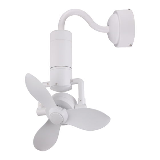
Page 5: Fan Structure Drawing (Wall Mount)
FAN STRUCTURE DRAWING (Wall Mount):... -
Page 6: Method Of Installation - Hugger/Flush Mount
METHOD OF INSTALLATION – HUGGER / FLUSH MOUNT INSTALLATION OF HANGER BRACKET: fig 1 fig 2 1) To use Four Expansion Setscrew to install the hanger bracket firmly (fig 1). 2) Install the ‘J’ hook onto the concrete ceiling and fasten firmly. Note the place of ‘J’... -
Page 7: C) Pre-Fix The Fan
PRE-FIX THE FAN: fig 5 1) Remove the Two screws from the hanger bracket (fig 5). It will be used on step ‘INSTALLATION OF FAN’. 2) Attach the safety wire cord to the expansion ‘J’ hook for safety purposes. Tighten the nuts firmly (fig 5). -
Page 8: D) Wiring Of Fan
WIRING OF FAN: 1) Total three groups of wires from the top of the main body: • White, Blue wires with small connector - for Synchronous Motor • Black(L1), Red (L2), Brown (L3) wires with big connector - for fan •... -
Page 9: Method Of Installation - Wall Mount
METHOD OF INSTALLATION – WALL MOUNT INSTALLATION OF HANGER BRACKET: 1) Use four Expansion Setscrew to install the hanger bracket to the wall firmly (fig 8). Note: The hanger bracket must be vertical to the floor. fig 8 INSTALLATION OF DOWNROD: fig 9 fig 10 1) Remove the ‘R’... -
Page 10: C) Hanging Of Fan
HANGING OF FAN: 1) Remove the ‘R’ pin, nut and cross pin from the coupler on the hanger bracket. 2) Thread the wires through the coupler and insert the downrod into the coupler (fig 11). fig 11 3) Install back the cross pin, nut and secured with the ‘R’ pin. The ‘R’ pin must be properly installed to prevent the cross pin from working loose. -
Page 11: E) Installation Of Canopy
INSTALLATION OF CANOPY: fig 13 fig 14 1) Remove the two screws from the hanger bracket and unscrew the other two screws from the hanger bracket out by ½. (fig 13) 2) Align and insert the canopy ‘L’ shape groove onto the hanger bracket screws, twist until its held tight. -
Page 12: Remote Control Manual (Wiring Diagram)
REMOTE CONTROL MANUAL (Wiring Diagram): 1. This manual is to use for the controller of fan. 2. Disconnect power supply before wiring. 3. Install the Receiver inside the canopy of fan to ensure proper protection. Adopt RF wireless digit emission technique, biunique controlled, coincident code rate is less than one millionth. -
Page 13: Remote Control Manual (Button Function)
REMOTE CONTROL MANUAL (Button Function): Model: DC-FC989RS Fan OFF Button 360° Revolve Angle Control (double press to change direction) Natural Wind Fan Speed Timer Light ON Button (not applicable for this model) Light OFF Button LED Indicated Light 1.5V Battery x 2pcs (Emitter) IMPORTANT: 1. -
Page 14: Maintenance Tips
MAINTENANCE TIPS: 1. Because of the fan’s natural movement, some connections may be loose. To check the support connections, brackets and blades attachments 2 times a year. Make sure they are all secured (It is not necessary to dismantle the entire fan from ceiling). 2. -
Page 15: Troubleshooting
TROUBLESHOOTING: PLEASE CHECK THE FOLLOWING BEFORE LODGING A SERVICE REPORT PROBLEM REASON SOLUTION Fan not 1) Main cables not 1) Check mains & sub circuit moving connected. breakers or fuse. 2) Check the line wires. 2) Check the line wires connections to the fan &... -
Page 16: Notes
NOTES: DRAWING SHOWING THE ASSEMBLY OF WIRES THROUGH FAN MOTOR SHAFT FOR DECORATIVE CEILING FAN...
Need help?
Do you have a question about the DC-360 and is the answer not in the manual?
Questions and answers
Que hacer si tengo varios ventiladores iguales y quiero controlar varios **** un solo control, pero funcionan solo un rato y se desemparejan
To control multiple Acorn DC-360 fans with a single remote, follow the pairing process for each fan one by one:
1. Turn ON the power supply to the first fan.
2. Within 30 seconds, press and hold the Emitter button on the remote for 5 seconds until a long beep is heard (this indicates successful pairing).
3. Repeat steps 1 and 2 for each additional fan, one at a time.
Note: You must pair each fan within 30 seconds of turning on its power. If pairing is not completed in that time, turn the power OFF and ON again before retrying.
If the fans disconnect shortly after pairing:
- Check for possible interference from other remote control products nearby.
- Ensure the batteries in the remote are not low, as this can affect signal strength.
- Move or eliminate sources of similar radio waves if possible.
This answer is automatically generated