Table of Contents
Advertisement
Available languages
Available languages
Quick Links
Operating and
assembly instructions
Bedienings- en
montagehandleiding
7534 10 11
Switch actuator 1gang
flush-mounted 10 A
Schakelactor 1-voudig
inbouw, 10 A
8034 10 11
Switch actuator 1gang
flush-mounted 10 A,
system-/easylink
Schakelactor 1-voudig
inbouw 10 A, easylink
Berker GmbH & Co. KG - Klagebach 38 - 58579 Schalksmühle/Germany - Tel. + 49 (0) 23 55/90 5-0 - Fax + 49 (0) 23 55/90 5-111 - www.berker.com -
1
Safety instructions
Electrical equipment may only be installed and
assembled by a qualified electrician in accord-
ance with the relevant installation standards,
guidelines, regulations, directives, safety and
z
z
accident prevention regulations of the country.
i
Failure to comply with these installation in-
structions may result in damage to the device,
fire or other hazards.
Hazard due to electric shock. Disconnect be-
fore working on the device or load. Take into
account all circuit breakers that supply danger-
ous voltages to the device or load.
Hazard due to electric shock. The device is not
suited for safe disconnection of the mains sup-
ply.
Hazard due to electric shock on the SELV or
PELV installation. Do not connect any loads for
low voltage SELV, PELV or FELV together.
These instructions are an integral component
of the product and must be retained by the end
user.
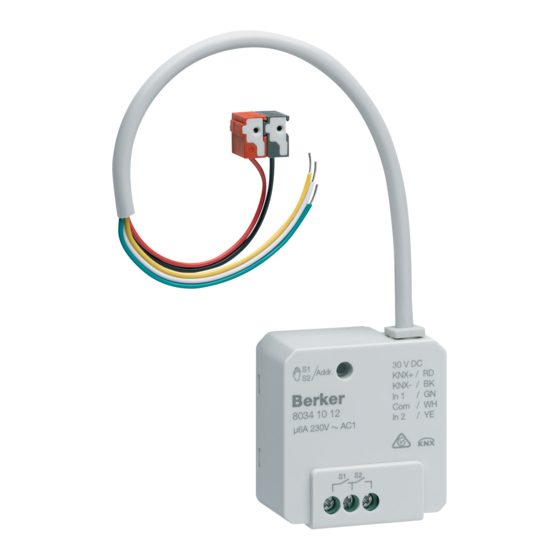
Design and layout of the device
(1)
Figure 1: device overview
(1) Illuminated button for manual operation/
programming button
(2) Connection of load(s)
(3) KNX bus connection cable
Function
System information
This device is a product of KNX system and corre-
sponds to the KNX guidelines. Detailed specialised
knowledge obtained from KNX training courses is
required for understanding. The planning, installa-
tion and commissioning of the device is carried out
with the help of KNX-certified software.
S-Mode start-up
The function of the device is software-depend-
ent. The software is to be taken from the product
database. You can find the latest version of the
product database, technical descriptions as well as
conversion and additional support programmes on
our website.
E-Mode start-up
The function of the device is configuration-de-
pendent. The configuration can also be done using
devices developed specially for simple setting and
This type of configuration is only possible with
devices of the easylink system. Easylink stands for
easy, visually supported start-up. Preconfigured
standard functions are assigned to the in/outputs
by means of a service module.
z
z
(3)
KNX+ /RD
KNX- /BK
S1
(2)
Functional description
The device receives telegrams from sensors or
other controllers via the KNX installation bus and
switches electrical loads with its relay contact.
Correct use
- Switching of electrical loads AC 230 V with po-
tential-free contact.
- Installation into wall box according to DIN
49073 (use deep box) or junction box sur-
face-mounted/flush-mounted.
Product characteristics
- Time switching functions.
- manual activation of the outputs on the device
possible, building site operation.
- Status display of the outputs on the device.
- Scene function.
- Forced position by higher-level controller.
Information for electricians
Installation and electrical connection
DANGER!
ç
Touching live parts can result in an
electric shock!
An electric shock can be lethal!
Disconnect the connecting cables
before working on the device and
cover all live parts in the area!
Connecting and installing the device
Connecting and installing the device
CAUTION!
ç
Impermissible heating if the load of
the device is too high!
The device and the connected cables
may get damaged in the connection
area!
Do not exceed the maximum current
carrying capacity!
CAUTION!
ç
When connecting the bus/extension
units and mains voltage wires in a
common wall box, the KNX bus cable
might come into contact with the
mains voltage.
The safety of the entire KNX
installation is at risk. Persons could
also get an electric shock even on
remote devices.
Do not place bus/extension units and
mains voltage terminals in a common
terminal compartment. Use a wall box
with a firm partition or separate boxes
(Figure 2).
SELV
KNX+ /RD
KNX- /BK
KNX+ /RD
KNX- /BK
S1
S1
230 V v
230 V AC
Figure 2: installation with separate terminal com-
partment
230 V v
KNX+ /RD
KNX- /BK
S1
6LE000479C
Advertisement
Table of Contents

Related Manuals for Berker 7534 10 11


Summary of Contents for Berker 7534 10 11
- Page 1 Berker GmbH & Co. KG - Klagebach 38 - 58579 Schalksmühle/Germany - Tel. + 49 (0) 23 55/90 5-0 - Fax + 49 (0) 23 55/90 5-111 - www.berker.com - 6LE000479C...
- Page 2 „ Hold down the button S1/Addr. (1) for > 10 s If you have a warranty claim, please contact the until it flashes red. point of sale or ship the device postage free with a KNX+ /RD KNX- /BK Warranty Warranty Resetting the device to the factory settings Resetting the device to the factory settings...
- Page 3 Houd de minimale afstand bussen netspanning en busaders van 4 mm aan. Berker GmbH & Co. KG - Klagebach 38 - 58579 Schalksmühle/Germany - Tel. + 49 (0) 23 55/90 5-0 - Fax + 49 (0) 23 55/90 5-111 - www.berker.com - 6LE000479C...
- Page 4 Te gebruiken in geheel Europa en in Zwitzerland 6LE000479A - 07/2014 Berker GmbH & Co. KG - Klagebach 38 - 58579 Schalksmü hle/Germany - Tel. + 49 (0) 23 55/90 5-0 - Fax + 49 (0) 23 55/90 5-111 - www.berker.com - 6LE000479C...
Need help?
Do you have a question about the 7534 10 11 and is the answer not in the manual?
Questions and answers