
Related Manuals for Broyhill CASTLE PINES LEGACY A102013104


Summary of Contents for Broyhill CASTLE PINES LEGACY A102013104
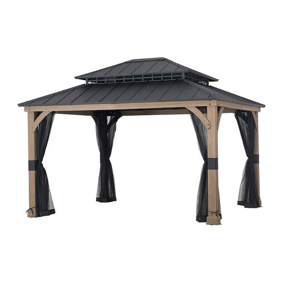
- Page 1 ASSEMBLY INSTRUCTIONS ITEM#: A102013104、A102013105 SKU#: 810494534、810494535 CASTLE PINES WOOD HARD TOP GAZEBO 1 (866) 578-6569 Need help? We are here for you! 24/7 • Toll Free...
- Page 2 GENERAL BEST PRACTICES FOR ASSEMBLY: • Please read and understand this entire manual before attempting to assemble or install the product. • Before beginning assembly of product, make sure all parts are present. Compare parts with package contents list and hardware contents list.
- Page 3 EXPLODED DRAWING 3/38...
- Page 4 PARTS LIST Label Part Number Description Part Image P005000320 P005000321 4/38...
- Page 5 5/38...
- Page 6 P000601735 P000601736 P000601859 P000601860 P000601901 P000601902 P000601903 P000900150 P000800287 P000700758 P000700759 P000700760 P000700761 P000700762 P000700763 6/38...
- Page 7 P000700764 P000700483 P000700924 P000700925 P001200038 HARDWARE LIST Label Part Number Description Part Image 7/38...
- Page 8 H040090005 H040090004 8/38...
- Page 9 HELPFUL HINTS • Tools needed and not included: • How many people needed for the installation work • Estimate assemble time: 150-180 minutes How many people needed for the installation work 9/38...
- Page 10 STEP 1 Secure the base (A) to the post (08) using screw (FF). 10/38...
- Page 11 STEP 2 Secure the base cover (09) to the post (08) using screw (GG). 11/38...
- Page 12 STEP 3 Connect the inner short and long beam (06/07) to the inner medial beam (05) using bolt (GG) and nut (LL/MM), tighten with wrench (Z2). 12/38...
- Page 13 STEP 4 Connect the lateral left and right long team (01/02) together, lateral left short beam (03) to the inner long beam (07) using bolt (CC) and nut (MM), tighten with wrench (Z2). 13/38...
- Page 14 STEP 5 Connect the assembled lateral long team (01/02) to the assmebled inner beam (05/07), assmebled lateral short team (03/04) to the assmebled inner beam (05/06) using screw (GG). 14/38...
- Page 15 STEP 6 Connect the assembled lateral long team (01/02/05/07) to the assmebled post (08/09/A) using bolt (AA), screw (BB), washer (HH) and nut (JJ), tighten with wrench (Z4). 15/38...
- Page 16 STEP 7 Connect the assembled lateral short team (03/04/05/06) to the assmebled post (08/09/A) using bolt (AA), screw (BB), washer (HH) and nut (JJ), tighten with wrench (Z4). 16/38...
- Page 17 STEP 8 Connect the big connector (B1) to the post (08) using screw (FF). 17/38...
- Page 18 STEP 9 d1=d2 Rt∠90 Connect the support bar (28/29) to the assembled beam and post using screw (DD), bolt (EE) and washer (II), tighten with wrench (Z2). 18/38...
- Page 19 STEP 10 Connect the big roof frame long side (E1) to the big roof frame short side (E2) with big top connector (E3) using bolt (OO), tighten with wrench (Z1). 19/38...
- Page 20 STEP 11 Connect the small connector for slant beam (B3) and the small connector for middle beam (B4) to the assembled big roof frame (E1/E2) using bolt (OO), tighten with wrench (Z1). 20/38...
- Page 21 STEP 12 Connect the slant beam for big roof (C1) to the assembled big roof frame (E1/E2) and the big connector (B1) using bolt (OO), tighten with wrench (Z1). 21/38...
- Page 22 STEP 13 Connect the middle beam for big roof (C2) to the middle beam connector (B2) using bolt (QQ), washer (RR) and nut (SS), tighten with wrench (Z1). 22/38...
- Page 23 STEP 14 Connect the assembled middle beam for big roof (C2/ B2) to the middle roof frame (E1/E2), assmebled middle beam (C2/B2) to the assmebled long beam (01/02/05/07) using bolt (QQ) and screw (FF), tighten with wrench (Z1). 23/38...
- Page 24 STEP 15 Connect the netting tube (D1/D2/D3/D4) to the slant and middle beam for big roof (C1/C2) using bolt (OO), tighten with wrench (Z1). 24/38...
- Page 25 STEP 16 Connect the slant and middle beam for small roof (G1/G2) to the small connector for small roof (F) using bolt (OO). Secure hook (H) to the small connector for small roof (F) using wrench (Z1) to tighten. 25/38...
- Page 26 STEP 17 Connect the assembled small roof to the small connector for beam (B3/B4) using bolt (OO/QQ), washer (RR) and nut (SS), tighten with wrench (Z1). 26/38...
- Page 27 STEP 18 Connect the small beam (I1/I2) to the small and middle beam (G1/G2) using bolt (OO), tighten with wrench (Z1). 27/38...
- Page 28 STEP 19 Connect the small roof lower beam (K1/ K2/K3) to the small and middle beam (G1/G2) using bolt (OO), tighten with wrench (Z1). 28/38...
- Page 29 STEP 20 Place small roof panel (P1/P2/P3/P4/P5) in the order as shown. 29/38...
- Page 30 STEP 21 Connect small roof panel (P1/P2/P3/P4/ P5) to the small roof lower beam (K1/K2/ K3) and slant beam (G1) using bolt (OO), tighen with wrench (Z1). 30/38...
- Page 31 STEP 22 Connect cover plate (M) to the slant beam (G1), top cover (N) to the small connector (F) using bolt (OO/PP), tighen with wrench (Z1). 31/38...
- Page 32 STEP 23 Connect long/short/side beam (J1/J2/J3) to the slant /middle beam (C1/C2) using bolt (OO), tighen with wrench (Z1). 32/38...
- Page 33 STEP 24 Connect big roof long lower beam (L1/L2/ L3/L4) and big roof short lower beam (L5/ L6) to the slant/middle beam (C1/C2) using bolt (OO), tighen with wrench (Z1). 33/38...
- Page 34 STEP 25 Place the big roof panel (Q1/Q2/Q3/Q4/ Q5) in the order as shown. 34/38...
- Page 35 STEP 26 Secure the big roof panel (Q1/Q2/Q3/ Q4/Q5) to the slant beam (C1) and the big roof lower beam (L1 - L6) using bolt (OO), tighten with wrench (Z1). 35/38...
- Page 36 STEP 27 Insert the cover plate (O) to the big roof connector (E3), then secure it to the slant beam (C1) using bolt (PP), tighten with wrench (Z1). 36/38...
- Page 37 STEP 28 Lock the plastic ring (TT) to the netting (R), then lock all the rings (TT) to the netting tube (D1/D2/D3/D4). 37/38...
- Page 38 STEP 29 Secure the gazebo to the ground using stakes (KK). 38/38...
Need help?
Do you have a question about the CASTLE PINES LEGACY A102013104 and is the answer not in the manual?
Questions and answers