
Related Manuals for Ametek ORTEC 428


Summary of Contents for Ametek ORTEC 428
- Page 1 Model 428 Detector Bias Supply Operating and Service Manual ® Printed in U.S.A. ORTEC Part No. 733220 062020 Manual Revision D...
- Page 2 Advanced Measurement Technology, Inc. ® ® a/k/a/ ORTEC , a subsidiary of AMETEK , Inc. WARRANTY ORTEC* warrants that the items will be delivered free from defects in material or workmanship. ORTEC makes no other warranties, express or implied, and specifically NO WARRANTY OF MERCHANTABILITY OR FITNESS FOR A PARTICULAR PURPOSE.
-
Page 3: Table Of Contents
CONTENTS WARRANTY ................ii SAFETY INSTRUCTIONS AND SYMBOLS . -
Page 4: Safety Instructions And Symbols
SAFETY INSTRUCTIONS AND SYMBOLS This manual contains up to three levels of safety instructions that must be observed in order to avoid personal injury and/or damage to equipment or other property. These are: DANGER Indicates a hazard that could result in death or serious bodily harm if the safety instruction is not observed. -
Page 5: Safety Warnings And Cleaning Instructions
SAFETY WARNINGS AND CLEANING INSTRUCTIONS DANGER Opening the cover of this instrument is likely to expose dangerous voltages. Disconnect the instrument from all voltage sources while it is being opened. WARNING Using this instrument in a manner not specified by the manufacturer may impair the protection provided by the instrument. -
Page 7: Description
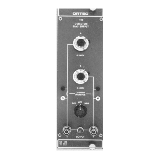
ORTEC MODEL 428 DETECTOR BIAS SUPPLY 1. DESCRIPTION The ORTEC 428 Detector Bias Supply provides bias WARNING voltage of either polarity for two semiconductor detectors. The voltages are selected independently This instrument produces voltages that can be by 10-turn, direct-reading potentiometers. The hazardous. -
Page 8: Installation
3.1. GENERAL 3.3. CONNECTIONS TO THE 428 The 428 contains an internal power supply that must The ORTEC 428 is compatible with ORTEC be used in conjunction with a Nuclear-Standard Bin detectors and with preamplifiers that have provisions and Power Supply such as the ORTEC 4001/4002. -
Page 9: Bias Voltage Selectors
If an electronic type of meter operated from the 4.4. BIAS VOLTAGE SELECTORS power line is used, the input circuit must be capable of floating above earth and power line ground so The desired bias voltage for each output is selected that the leakage to ground does not load the bias by its associated 10-turn potentiometer. -
Page 10: Undesirable Leakage Currents
4.7. DETERMINATION OF ACTUAL DETECTOR BIAS In addition to its use as an indicator of physical condition of the detector, the detector current allows accurate determination of the actual bias voltage across the detector, This actual voltage differs from that indicated by the bias selector dials by the amount of drop in voltage across the detector load and filter resistors due to the detector current. -
Page 11: Detector Considerations At High Bias Voltages
4. Ensure that the Polarity Selection switch on the 8. Set the output voltage to zero and connect output ORTEC 428 is in the Off position. A to the ac-coupled input of an oscilloscope with a coaxial cable. Increase the output voltage to 500 V 5. -
Page 12: Adjustments
8. Reduce the potentiometer to zero and check the 5.2. ADJUSTMENTS output voltage versus the potentiometer dial reading at several points. Resistors R15 and R 17 provide a If the output voltage does not agree with the dial method of measuring the detector current with a reading, it should be recalibrated using the following voltmeter. - Page 13 Bin/Module Connector Pin Assignments For Standard Nuclear Instrument Modules per DOE/ER-0457T. Pin Function Pin Function +3 V Reserved - 3 V Reserved Spare bus Reserved Reserved bus Spare Coaxial Spare Coaxial *28 +24 V Coaxial *29 - 24 V 200 V dc Spare bus Spare Spare...
Need help?
Do you have a question about the ORTEC 428 and is the answer not in the manual?
Questions and answers