Advertisement
Quick Links
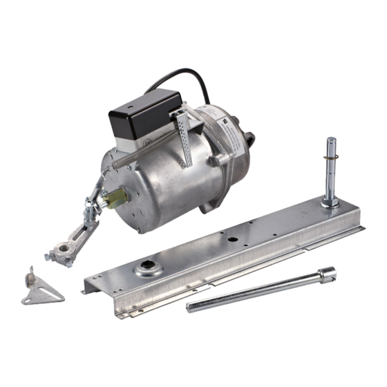
DS-3153 with Universal Mounting Bracket Installation
10
Item
1
2
3
4
5
6
7
8
9
10
11
12
13
14
Note: The DS-3153-1 is factory assembled for outside duct mounting. The components are
shown separate for clarity when changing to frame mounting is required.
T
ools Required
•
standard screwdriver (6 inch shank with
5/16 inch blade)
•
open end wrench, adjustable to 1 inch
© 1996 Johnson Controls, Inc.
Part No. 34-188-26, Rev. —
Code No. LIT-2681077
12
10
14
8
9
7
Description
Blade Pin Extension with clip
Universal Mounting Bracket Assembly with bronze bearing
Flange Nuts
Reinforcement Washers
Pivot Post
E-ring Clip, 1 spare
Swivel Ball Joint
Crank Arm
Blade Arm Connection
Modified Spacing Washers for Standard Value Blades
1/4 inch diameter x 13/32 inch (10 mm) Drive Rivet
Reinforcement Link
No. 12-24 x 1/2 inch (13 mm) Hex-head, Thread-forming Screws
No. 12 x 1/2 inch Type AB Screws, Pan-head
Actuator (not shown)
Damper and Actuator Manual 268.1
Actuator Literature Section
1
2
4
4
6
3
5
•
drill bit (3/16 inch, 4.8 mm, No. 9 or 10) and drill
•
hammer
•
nut driver, 5/16 inch
Installation Bulletin 3153
Issue Date 0596
3
Qty
1
1
2
2
1
3
1
1
1
2
1
1
5
6
1
1
Advertisement

Related Manuals for Johnson Controls DS-3153


Summary of Contents for Johnson Controls DS-3153
- Page 1 No. 12-24 x 1/2 inch (13 mm) Hex-head, Thread-forming Screws No. 12 x 1/2 inch Type AB Screws, Pan-head Actuator (not shown) Note: The DS-3153-1 is factory assembled for outside duct mounting. The components are shown separate for clarity when changing to frame mounting is required. ools Required •...
- Page 2 H ead B ear in g Crank Arm P ivot B lade P in E xtension P ost U niver sal M ounting B racket D uct Figure 1: Duct Mounting Components 2 Acutator Literature—DS-3153 with Universal Mounting Bracket Installation Bulletin...
-
Page 3: Universal Mounting Bracket Assembly
Note: On ducts with outside insulation, the universal mounting bracket can be attached to the duct with the spacers supplied and the No. 12-24 x 2 inch thread forming pan-head screws. Acutator Literature—DS-3153 with Universal Mounting Bracket Installation Bulletin 3... - Page 4 5. Thread the nut onto the pivot post in the channel of the universal mounting bracket and tighten. 2. Remove the nut securing the pivot post from the universal mounting bracket channel. 4 Acutator Literature—DS-3153 with Universal Mounting Bracket Installation Bulletin...
-
Page 5: Universal Mounting Bracket Installation
Figure 11. Do not tighten at this time. For right-hand CCW open dampers, position the link above the blade centerline. For right hand CW open dampers, position the link below the blade centerline. Acutator Literature—DS-3153 with Universal Mounting Bracket Installation Bulletin 5... - Page 6 6 Acutator Literature—DS-3153 with Universal Mounting Bracket Installation Bulletin...
-
Page 7: Actuator Installation
“C” position in long slot for normally closed applications and midway between “C” and “D” in the short slot for normally open application on airfoil blade dampers. Acutator Literature—DS-3153 with Universal Mounting Bracket Installation Bulletin 7... - Page 8 Controls Group FAN 268.1 507 E. Michigan Street Damper and Actuator Manual P.O. Box 423 Printed in U.S.A. Milwaukee, WI 53201 8 Acutator Literature—DS-3153 with Universal Mounting Bracket Installation Bulletin...
Need help?
Do you have a question about the DS-3153 and is the answer not in the manual?
Questions and answers