
Related Manuals for Johnson Controls DWCR2


Summary of Contents for Johnson Controls DWCR2
- Page 1 DWCR2 User Manual DWCR2 Wired Controller Thank you for choosing the DWCR2 Wired Controller. Please read this user manual carefully before operation and retain it for future reference. Lit 12012511...
- Page 2 User Notices For correct installation and operation, please read all instructions carefully. Before reading the instructions, please be aware of the following items: It is prohibited to install the wired controller in wet places or direct sunlight. Do not knock, throw or frequently disassemble the wired controller. ...
-
Page 3: Table Of Contents
Contents 1 Display ................... 1 1.1 Appearance ................1 1.2 Instructions for Related Displayed Symbols......2 2 Buttons .................. 3 2.1 Button Graphics ................ 3 2.2 Function Instructions of Buttons ..........4 3 Operation Instructions ............4 3.1 Menu Structure ................4 3.2 On/Off .................. - Page 4 3.12 Lock Setting ................33 4 Installation Instructions ............34 4.1 Parts and Dimension of Wired Controller ........ 34 4.2 Installation Requirements ............35 4.3 Installation Methods ..............36 4.4 Disassembly ................37...
-
Page 5: Display
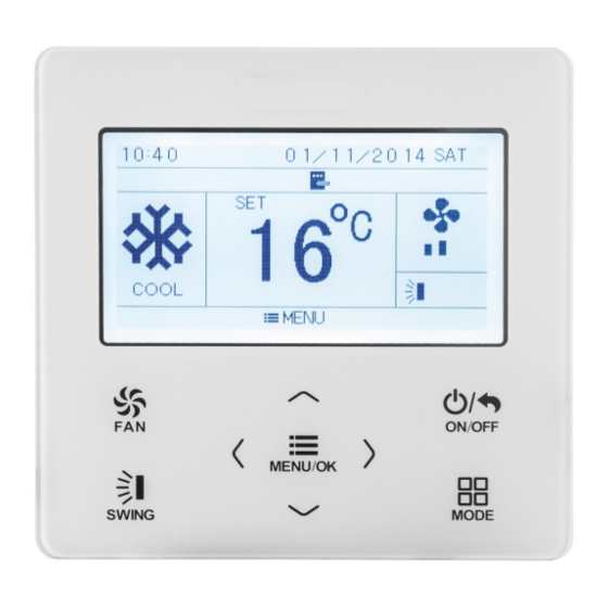
Wired Controller DWCR2 1 Display 1.1 Appearance Fig.1 Appearance of wired controller... -
Page 6: Instructions For Related Displayed Symbols
Wired Controller DWCR2 1.2 Instructions for Related Displayed Symbols Symbols Instructions Up and down louver (swing) function Left and right louver (swing) function This row left intentionally blank. Sleep function Auto mode Cooling mode Dry mode Fan mode Heating mode This row left intentionally blank. -
Page 7: Buttons
Wired Controller DWCR2 Remind to clean the filter Timer on status Access card absent, off status or unoccupied status Quiet function Function lock 2 Buttons 2.1 Button Graphics Fig. 2 Button graphics... -
Page 8: Function Instructions Of Buttons
Wired Controller DWCR2 2.2 Function Instructions of Buttons Button name Button Function Set low speed, low-medium speed, medium speed, medium-high speed, high speed, turbo and auto speed. (1) Set temperature ∧ (2) Set parameter ∨ (3) Move option cursor (1) Turn on or turn off unit... -
Page 9: On/Off
Wired Controller DWCR2 Fig. 3 Menu structure 3.2 On/Off When the wired control is on main page, press ON/OFF button to turn on the unit. Press ON/OFF button again to turn off the unit. The interfaces of On/Off status are... -
Page 10: Mode Setting
Wired Controller DWCR2 Fig. 4 Off interface Fig. 5 On interface 3.3 Mode Setting Under On status, pressing MODE button can set mode as: Note: If save function is on, auto mode is not available. -
Page 11: Temperature Setting
Wired Controller DWCR2 3.4 Temperature Setting Under unit on status, pressing “ ” or “ ∨ ” button on the main page increases or ∧ decreases set temperature by 1℉(1℃); holding “ ∧ ” or “ ∨ ” button increases or decreases set temperature by 1℃(1℉) every 0.3s. - Page 12 Wired Controller DWCR2 → → → → → → → → → → → closed → Select up&down and left&right louver through “<” or “>” button. Select left&right louver, and left&right swing angle is adjusted as below: → → →...
- Page 13 Wired Controller DWCR2...
-
Page 14: Functions Setting
Wired Controller DWCR2 Fig. 7 Swing setting 3.7 Functions Setting Press MENU/OK button on main page to enter main menu page. Press “∧” or “∨” or “<” or “>” button to select the function setting symbol. Then press MENU/OK button to enter user function setting page. Press “∧” or “∨” button to select specific function item. - Page 15 Wired Controller DWCR2 Fig. 8 Function setting...
- Page 16 Wired Controller DWCR2 3.7.1 Sleep Function Setting Enter user function page, and press “ ” or ∨ ” button to select sleep function, “ ∧ and press “<” or “>” button to turn on or turn off sleep function with auto saving.
- Page 17 Wired Controller DWCR2 3.7.2 This section left intentionally blank 3.7.3 I-DEMAND Function Setting After entering user function page, press “ ” “ ∧ or ∨ ” button to select IDEMAND function option and press “<” or “>” button to turn on or turn off this function with auto saving.
- Page 18 Wired Controller DWCR2 3.7.4 Absence Function Setting After entering user function page, press “ “ ∧ ” or ∨ ” button to select holiday function option and press “<” or “>” button to turn on or turn off this function with auto saving.
- Page 19 Wired Controller DWCR2 3.7.6 Save Function Setting Enter user function page. Press “ “ ∧ ” or ∨ ” button to select save function and press “<” or “>” button to turn on or turn off save function. Press MENU button to enter save function setting page.
- Page 20 Wired Controller DWCR2 3.7.9 Quiet Function Setting Enter the save function setting page, and press “<” or “>” button to select quiet function. Press “<” or “>” button to turn on or turn off this function with auto saving. Note: This function is only available in cooling mode, heating mode, and auto mode.
- Page 21 Wired Controller DWCR2 Whenever you turn off this function, the unit’s operating time is zero. 3.7.11 Fahrenheit Temperature Setting Enter the user function page, press ““ ∧ ” or ∨ ” button to select Fahrenheit temperature function, and press “<” or “>” button to turn on or turn off this...
-
Page 22: Unit Status View
Wired Controller DWCR2 3.8 Unit Status View Press MENU button to enter the menu. Select the function symbol to be viewed. Then, press MENU button to enter view function page. Press “∧” or “∨” button to select status view function. Press MENU button to enter unit status view page. Press... - Page 23 Wired Controller DWCR2 This page left intentionally blank...
-
Page 24: Current Error View
Wired Controller DWCR2 3.9 Current Error View When error occurs in the unit, error symbol is displayed on the main page of wired controller to indicate that the system has an error. In this case, you can enter error view page to view the current error. - Page 25 Wired Controller DWCR2 Fig. 10 Current Error View...
-
Page 26: Timer Setting
Wired Controller DWCR2 3.10 Timer Setting The wired controller can set 6 kinds of timers: one time clock timer, everyday timer, one week timer, two week timer, countdown timer on, and countdown timer off. Select timer symbol after entering menu page. Press MENU button to enter timer setting page. - Page 27 Wired Controller DWCR2 In timer function setting page, when one time timer is selected, press “<” or “>” button to turn on or turn off this timer function. Press MENU button to enter timer time setting page, as shown in Fig. 12.
- Page 28 Wired Controller DWCR2 3.10.2 Daily Timer In daily timer, user can set eight segments of timer individually. The individual segment is valid only when it is turned on. In each segment, you can set the time, unit ON/OFF, set temperature in cooling (it is valid only when the current mode is cooling), set temperature in heating (it is valid only when the current mode is heating).
- Page 29 Wired Controller DWCR2 3.10.3 Weekly Timer The user can set the everyday timer content for a week. In each day, the user can set eight segments of timer content. The unit will execute corresponding timer setting for a week. After entering weekly timer setting page, press “<” or “>” button to select the day to be set.
- Page 30 Wired Controller DWCR2...
- Page 31 Wired Controller DWCR2 Fig. 14 Weekly timer setting 3.10.4 Two Week Timer The user can set the everyday timer content for two weeks. In each day, the user can set eight segments of timer content. The unit will execute corresponding timer setting for two weeks.
- Page 32 Wired Controller DWCR2 current week as first week or second week. Press MENU button to save current week setting. Please refer to Fig. 15. Fig. 15 Setting of current week After entering two week timer menu page, press “ ” or “...
- Page 33 Wired Controller DWCR2 3.10.5 Countdown Timer Countdown timer includes timer on and timer off. Unit On/Off after a desired hour can be set. In unit on status, timer off can be set, or timer off and timer on can be set simultaneously.
- Page 34 Wired Controller DWCR2 After entering timer off setting page, press “ ” “ ∧ or ∨ ” button to increase or decrease timer time by 0.5 h. Press BACK button to return to the last page. Please refer to Fig. 17.
-
Page 35: Clock Setting
Wired Controller DWCR2 3.11 Clock Setting 3.11.1 Time Format Setting The user can set the time format in 12-hour system or 24-hour system. Select clock symbol in menu page and then press MENU button to enter clock setting page. Press “∧” or “∨” button to select time format and then press “<” or “>” button to select 12-hour system or 24-hour system. - Page 36 Wired Controller DWCR2 Press “<” or “>” button to select setting items: hour, minute, year, month, day; press “∧” or “∨” button to set the value and then press MENU button to save setting. Please refer to Fig. 19. Fig. 19 Clock setting...
-
Page 37: Lock Setting
Wired Controller DWCR2 3.12 Lock Setting Select lock symbol in menu page and then press MENU button to enter lock setting page. Press “∧” or “∨” button to select the item to be locked and then press “<” or “>” button to lock or unlock. Please refer to Fig. 20. Items that can be locked: ON/OFF, mode setting, temperature setting, fan speed setting, key lock. -
Page 38: Installation Instructions
Wired Controller DWCR2 4 Installation Instructions 4.1 Parts and Dimension of Wired Controller Fig. 21 Dimension of wired controller Fig. 22 Parts of wired controller... -
Page 39: Installation Requirements
Wired Controller DWCR2 Base of wired Panel of wired Name Screw M4X25 controller controller Quantity 4.2 Installation Requirements (1) DO NOT install the wired controller in damp places; (2) DO NOT install the wired controller in direct sunlight; (3) DO NOT install the wired controller in a place near high... -
Page 40: Installation Methods
Wired Controller DWCR2 4.3 Installation Methods Fig. 23 Installation diagram for wired controller Fig. 23 is the simple installation process of wired controller; please pay attention to the following items: Before installation, please cut off the power for indoor unit;... -
Page 41: Disassembly
Wired Controller DWCR2 this wire through the “ ” hole at the bottom side of the base of the wired controller; Screw the base of the wired controller onto the wall and then use screw (3). M4×25 to attach the base and back plate on the wall together. - Page 44 © 2018 Johnson Controls, Inc. LIT-12012511 Revised October 2020...
Need help?
Do you have a question about the DWCR2 and is the answer not in the manual?
Questions and answers