Table of Contents
Advertisement
Quick Links
WARNINGS
• TO AVOID FIRE, SHOCK, OR DEATH, TURN OFF POWER at circuit breaker or fuse and test that power is off before wiring!
• For indoor applications only.
• If you are unsure about any part of these instructions, consult an electrician.
• To be installed and/or used in accordance with appropriate electrical codes and regulations.
DESCRIPTION
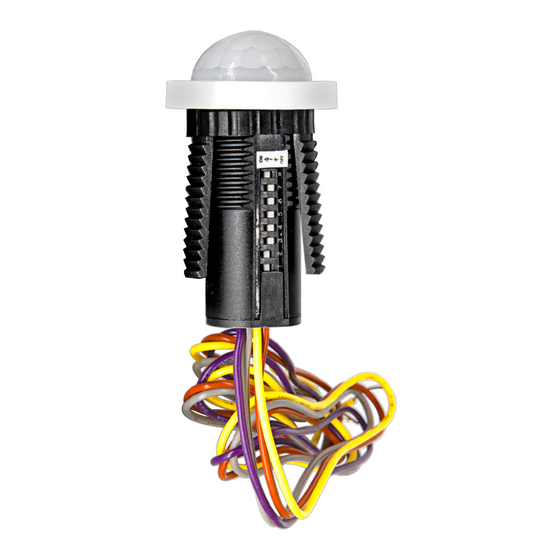
• Leviton® Cat. No. ZLS05-ILW is a low-voltage occupancy and daylight harvesting sensor designed for installation directly into an indoor lighting fixture. The sensor is designed
for individual control of 0-10VDC dim-to-off LED drivers, with an auxiliary power supply of 12-24VDC required to power the sensor. Configure the dimming profile and output
settings of the sensor using DIP switches or Leviton Cat. No. ZLS0R-RA1, IR remote control.
• An integrated daylight harvesting sensor can be enabled by using the IR remote control to measure the available ambient light and to adjust the lighting output of the fixture
between user-defined task and stand-by lighting levels. When disabled, the fixture will dim to the stand-by level after the hold time has expired. If occupancy is not detected, the
fixture turns OFF at the end of the stand-by time.
• The sensor uses Passive Infrared (PIR) detection technology to monitor for occupancy, and controls the fixture based on user-selectable settings. PIR detection may be disabled
using the IR remote control. The fixture will remain ON regardless of occupancy and if enabled, daylight harvesting will continue to operate.
• The sensor may be installed into your fixture by the fixture manufacturer. When the sensor is pre-installed in a fixture, refer to the fixture documentation for installation methods,
means and requirements.
NOTES:
• Requires 0-10V dim-to-OFF driver with AUX power supply.
• If pre-installed into a fixture, and you are replacing, refer to fixture
instructions for appropriate installation.
• Sensor is designed for a mounting height of 8 ft., with a fixture
spacing-to-mounting height ratio of 1:1.
• Maximum mounting height is 10 ft.
Specifications
Input Rating
Dim Control Output
Purpose of Control
IP Rating
Operating Temperature
Storage Temperature
INSTALLATION
WARNING: TO AVOID FIRE, SHOCK, OR DEATH, TURN OFF POWER at circuit
breaker or fuse and test that power is off before wiring!
1. Confirm factory default DIP switch settings and configure as required.
• Task Level: 100%
• Occupied Timeout: 10 seconds
• Stand-by Level: 20%
• Stand-by Time: 30 minutes
2. Position sensor in 7/8 in. diameter round punch hole in fixture and secure, using
included plastic lock nut.
• See installation diagram.
3. Connect sensor to LED driver and apply power.
• See wiring diagram.
• Use 18 AWG or larger wires suitable for at least 90°C.
4. At first power-up, the sensor may require a warm-up period of up to 40 seconds.
5. Observe red LED indicator to confirm sensor is operational.
FOR OPTIMAL PERFORMANCE:
The ZLS05 Solo Sensor lens establishes dozens of zones of detection. The sensor is sensitive to the heat emitted by the human body. To trigger the sensor, the source of heat
must move from one zone of detection to another. The device is most effective in sensing motion across its field-of-view, and less effective sensing motion towards or away from
its field-of-view. Keep this in mind when selecting the installation location. Note that occupancy sensors respond to rapid changes in temperature, so care should be taken not to
mount the device near a climate-control source (i.e. radiators, air exchanges, and air conditioners). Hot or cold drafts will look like body motion to the device and will trigger it if the
unit is mounted too close. It is recommended to mount the Occupancy Sensor at least 6 ft. away from a climate-control source. In addition, it is also recommended NOT to mount
the Occupancy Sensor directly under a large light source. Large wattage bulbs (greater than 100W incandescent) give off a lot of heat and switching the bulb causes a temperature
change that can be detected by the device. Mount the Occupancy Sensor at least 6 ft. away from large bulbs. If it necessary to mount the device closer, lower the wattage of the
bulb directly overhead. For applications involving daylighting harvesting, please ensure sensor and fixture are installed in locations that receive sufficient ambient light.
OPERATION
The ZLS05 Solo Sensor is designed to operate per configuration settings set by DIP switch, or using the ZLS0R-RA1 remote control. See user manual for more information on
ZLS0R-RA1 features and operation.
INSTALLATION INSTRUCTIONS
Class 2, 12-24VDC, 50mA
0-10V, 25mA sinking
Energy Management Equipment
IP20
-20°C to 70°C (-4°F to 158°F)
-20°C to 85°C (-4°F to 185°F)
Solo Sensor
TM
Cat. No. ZLS05-ILW
Coverage Top View
15 ft.
10 ft.
5 ft.
0 ft.
5 ft.
10 ft.
15 ft.
15 ft.
10 ft.
5 ft. 0 ft.
5 ft.
10 ft.
15 ft.
Minor Motion
Major Motion
L
N
Coverage Side View
0 ft.
30 ft.
10 ft.
12 ft.
7 ft.
5 ft. 3 ft.
Wiring and Installation Diagram
Dimming
Driver
(22.2mm)
DI-000-ZLS05-05B
ENGLISH
7 ft.
12 ft.
LED
7/8 in.
Advertisement
Table of Contents

Related Manuals for Leviton Solo Sensor ZLS05-ILW


Summary of Contents for Leviton Solo Sensor ZLS05-ILW
- Page 1 DESCRIPTION • Leviton® Cat. No. ZLS05-ILW is a low-voltage occupancy and daylight harvesting sensor designed for installation directly into an indoor lighting fixture. The sensor is designed for individual control of 0-10VDC dim-to-off LED drivers, with an auxiliary power supply of 12-24VDC required to power the sensor. Configure the dimming profile and output settings of the sensor using DIP switches or Leviton Cat.
- Page 2 LIMITED 5 YEAR WARRANTY AND EXCLUSIONS Leviton warrants to the original consumer purchaser and not for the benefit of anyone else that this product at the time of its sale by Leviton is free of defects in materials and workmanship under normal and proper use for five years from the purchase date.
Need help?
Do you have a question about the Solo Sensor ZLS05-ILW and is the answer not in the manual?
Questions and answers